
3-Ways to Interface a 7-Segment Display with a Microcontroller
We use 7-segment displays in our electronics systems because they are a less complex device for displaying numbers. In most of the electronics systems, we prefer 7-segment displays over graphical displays because graphical displays are more complex than 7-segment displays, and also making a program for graphical displays is more complicated.
For interfacing a graphical display with an embedded system, it requires more program and data memory space. For a small embedded system, it may not be a good choice. 7-segment displays are simple to understand and use. In this post, we'll learn how we can interface a 7-segment display to a microcontroller in different ways.
First Method
It is straightforward, and most of you are familiar with it. In this method, eight digital output pins (including dot segment) are required to interface with a 7-segment display. Each pin of the 7-segment is needed to connect to the individual digital output pin. The microcontroller has ports, and most of the ports have eight pins.
In the case of the development board, the number of pins per port may be less than eight. If ports are available, then one port is required to interface the display.
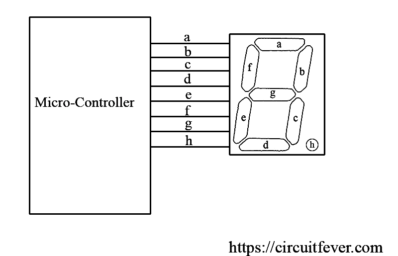
Based on the display configuration, it determines whether it is the common anode or common cathode. A single bit is required to make the segment visible or not.
Second Method
This method requires an additional device or Integrated Circuit (IC) named 7447 IC. This is a digital integrated circuit known as a BCD to 7-segment display. The name tells us everything. This IC is made for driving the 7-segment display. It takes BCD input and makes appropriate output so that the display can show a similar BCD number.
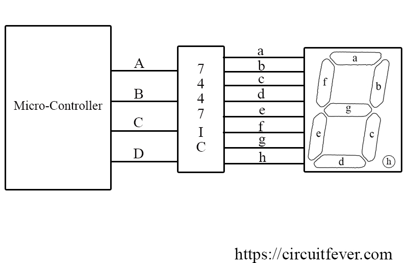
For example, BCD number 7 has a binary equivalent of 0111. Where 0 is LSB and 1 is MSB. If this binary number is given to the IC as input, the IC makes the a,b, and c pins LOW (For a common anode configuration) so that the display shows the number 7. In this method, four pins of the microcontroller are sufficient to display a number.
Again, it is as simple as the first method, but the connection must be done correctly. A single mistake in the pin connection can result in an incorrect number display.
Third Method
This method also requires an additional integrated circuit. This method requires a SIPO (Serial Input Parallel Output) Shift register. Only two output pins of the microcontroller are required to make this thing work.
There are eight pins in the 7-segment display, so an 8-bit shift register is required for a single 7-segment display.
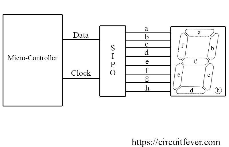
There are two pins, one is a data pin and the other is a clock pin. Data is shifted from one flip-flop to the other on every clock pulse.
For example, number 7 can be shown on the display by making a,b, and c LOW and the rest HIGH (For a common anode configuration). The binary equivalent for displaying number seven is a,b,c,d,e,f,g,h --> 00011111.
First, 1 is given to the data pin, and for the first clock, the data one enters the shift register. After that, the second bit is given to the data pin, and when the next clock comes, the second bit enters the shift register. The rest will be done in the same way.
When all bits enter the shift register, the setup is ready for the display.