Arithmetic and Logical Unit (ALU) Verilog Code
The arithmetic and Logical Unit(ALU) is the digital circuit used by the processor for performing various arithmetic and logical operations like addition, subtraction, logical AND operation etc. It may have one or more than one operand and an opcode. The opcode will tell the ALU which operations to perform. If the processor is n-bit then ALU will perform the operation on n-bit operand. The length of the opcode given to the ALU will decide at maximum how much ALU can perform operations.
ALU Verilog Code
We'll describe a simple ALU in Verilog HDL with only combinational circuits for 8-bit processor. For simplicity, only eight operations are chosen but you can design an ALU. Below is the code for a 8-bit ALU which can perform addition, subtraction, division, multiplication, logical AND, OR, NOT and EX-OR.
//8-bit arithmetic and logical unit
module alu(
input [2:0]opcode,
input [7:0]OperandA,OperandB,
output reg [7:0]result
    );

always @(*)begin
case(instruction)
3'b000:
    result = OperandA + B;
3'b001:
    result = OperandA - B;
3'b010:
    result = OperandA / B;
3'b011:
    result = OperandA * B;
3'b100:
    result = OperandA & B;
3'b101:
    result = OperandA | B;
3'b110:
    result = ~OperandA;
3'b111:
    result = OperandA ^ OperandA;
default:
    result = 0;
    endcase
end

endmodule
The above code has processing elements(PE) and MUX. We have to perform 8 operations so, 8X1 MUX is required to select the desired operation. The length of the inputs is 8-bit so we require eight 8X1 MUX. The above code is described using behavioural modeling. The case statement will be synthesised to MUX and each processing element will be synthesised to a combinational circuit.
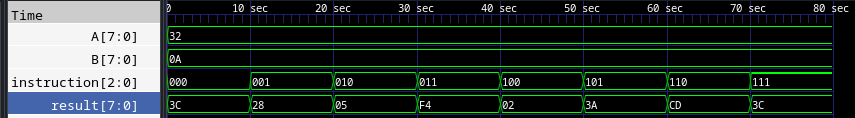
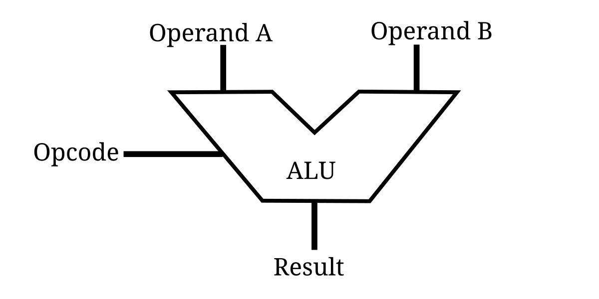
If the instruction is 000, it performs the addition operation of the operands A and B and output is available at the output of the MUX, 001 performs the subtraction operations and so on. The block diagram of described ALU is shown below:
ALU Testbench
module alu_tb;

reg [2:0]instruction;
reg [7:0]A,B;
wire [7:0]result;

alu uut(instruction,A,B,result);

integer i;

initial begin
A = 50; B = 10; instruction = 0;

for(i = 1; i < 8; i = i+ 1)begin
    #10
    instruction = i;
end

#10
$finish();

end

endmodule
Output Waveform