Clamper Circuits using Diode
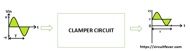
It is an arrangement of diode and capacitor which is used to shift the positive and negative peak of a signal at some desired dc level by not changing the shape of the signal.
Clamper Circuit is divided into 2 Types as following:
- Positive Clamper Circuit
- Negative Clamper Circuit
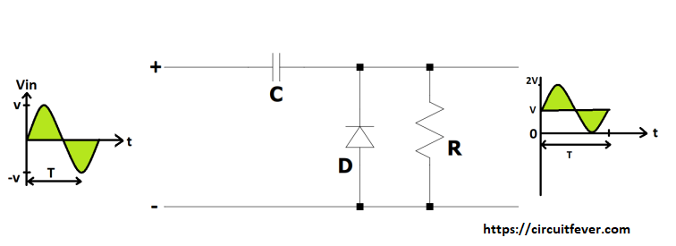
1. Positive Clamper Circuit
In positive clamper circuit , the circuit is used to shift the input negative peak to zero level. This can be achieved and designed by diode , capacitor and resistor .
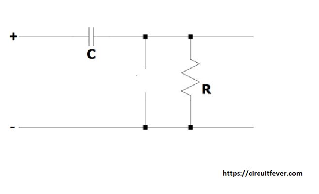
Circuit Diagram of positive clamper is shown below :

Initially in positive half cycle , Diode act like as an open circuit due to reverse biased condition and the capacitor will get charged but capacitor will not equal to peak voltage V due to high RC time constant. So the output signal will remain same as an input signal. (So , we will not add this cycle in waveform.)
Now in negative half cycle ,polarity of signal will get reversed, Diode will get forward biased and act like as a closed and short circuit. So the capacitor will get charged to peak voltage V . So by using KVL, the output voltage is equal to Vin + V = 0V.(For , this negative half cycle).
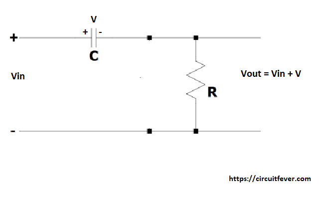
So for next positive half cycle , diode act like as an open circuit and by using KVL , Vout = Vin + V=2V. (Here V is charged voltage by capacitor.) and for negative half cycle , it will remain as an open circuit due to reverse biased condition and Output signal is equal to (Vin + V).
2. Negative Clamper Circuit
In negative clamper circuit , the circuit is used to shift the input positive peak to zero level. This can be achieved and designed by diode , capacitor and resistor.
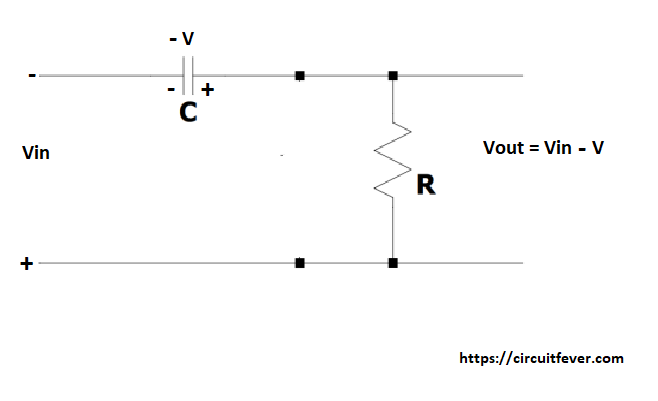
Circuit diagram of negative clamper circuit as shown below:
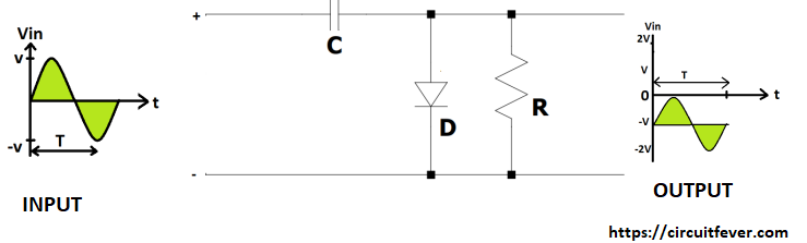
Initially in positive half cycle , Diode act like as an closed circuit so the capacitor will get charged to peak voltage V . By using KVL , output voltage is equal to Vin - V = 0.
now in negative half cycle , polarity of signal will get reversed, Diode will be reversed biased and act like as an open circuit. and the output voltage of circuit is equal to -Vin -V = -2V