8-bit Counter Implementation On FPGA using Verilog
Counter is a digital circuit which keep track of the counting like time, numbers etc. Counter circuit is present in wide range of electronics devices like a digital clock or stopwatch (where counter counts seconds, minutes, hours etc), a counter in your car's dashboard which counts how much distance your car has covered till now and many more.
This is a sequential circuit which requires a clock and it can be synchrounous or asynchronous. In this block post we'll learn how to make a decoder for a seven segment display. Most of the FPGA development board has seven segment display we can use that for this implementation. If not then you can use external seven segment display and connect that with the PMOD connector.
What we require?
- A FPGA Board
- A Synthesis tool (Vivado)
- USB Cable
- LED's (If it is not available in the board)
How to make?
You may want to count any quantity by in this post we'll implement which counts clock pulses so that later we can use this to count some other quantity like time (seconds). First, we make a module for counter and we'll describe our counter in it. The positive edge triggered clock pulse counter which counts each positive edge clock applied to the module. If the module can count pulse, we can convert our quantity (like seconds) to clock pulse and we'll end up with a counter.
Verilog Description
The Verilog description of a positive edge triggered counter is described below. This module has an input clock, asynchronous reset. The module also have input stop and 8-bit output. The Verilog code is simple to understand,
In each positive edge of input clock (clk), register count is incremented by one binary digit provided that stop input is logic 0. If stop is logic 1, it holds the count value. The reset is asynchronous, it doesn't matter clock pulse is reached or not, if reset is logic 0, it reset the count value to 0. It is 8-bit counter hence it counts form 0-255. You can increase the count register if you want to count more.
module counter8bit(
    input clk,
    input reset,
    input stop,
    output reg [7:0]count
    );

always @(posedge clk or negedge reset) begin
    if(~reset) begin
        count <= 0;
    end else begin
        if(stop)
            count <= count;
        else
            count <= count + 1;
    end
end

endmodule
Now, our counter is ready and we'll use this to count seconds. For that first we have to create a clock pulse which has a period of 1 second. So, each period will have one positive edge. If we apply this to our counter, the counter value is incremented in each seconds. This is how we can count seconds.
I am using Nexys4 DDR FPGA board and it has 100MHz of system clock. Using clock divider, we will create a clock of 1 second. Below is the Verilog description for clock divider which generates a clock which has a period of 1 second. It also has one counter which counts the clock pulse. When 100 Mega clock puse is counted, It resets the count. Based on the count value, the output is toggle. If count values is ledd than 50 Megs clock pulse, output is 1 else output is 0.
We have created a counter which resets in 1 second and half of the second, output is 1 and another half is 0. It generates a clock which has period of w second. Now we are left with the connections.
module clk_div(
    input clk,
    output reg clk_out
    );

reg [31:0]count;

always @(posedge clk) begin
    if(count == 99999999)
        count <= 0;
    else
        count <= count + 1;

clk_out <= (count<5000000)?1:0;
end

endmodule
The top module of our second counter is which is described in Verilog is given below. This module has input clock, reset stop and 8-bit counter output. We've instanciated both clock divider and counter circuit. 100 MHz clock is given to the clock divider and output of 1 second clock form clock divider is connected to the main counter.
module counter8bit_top(
    input clk,
    input reset,
    input stop,
    output [7:0]count
    );

counter8bit counter_int(clk_out,reset,stop,count);
clk_div clk_div_inst(clk,clk_out);

endmodule
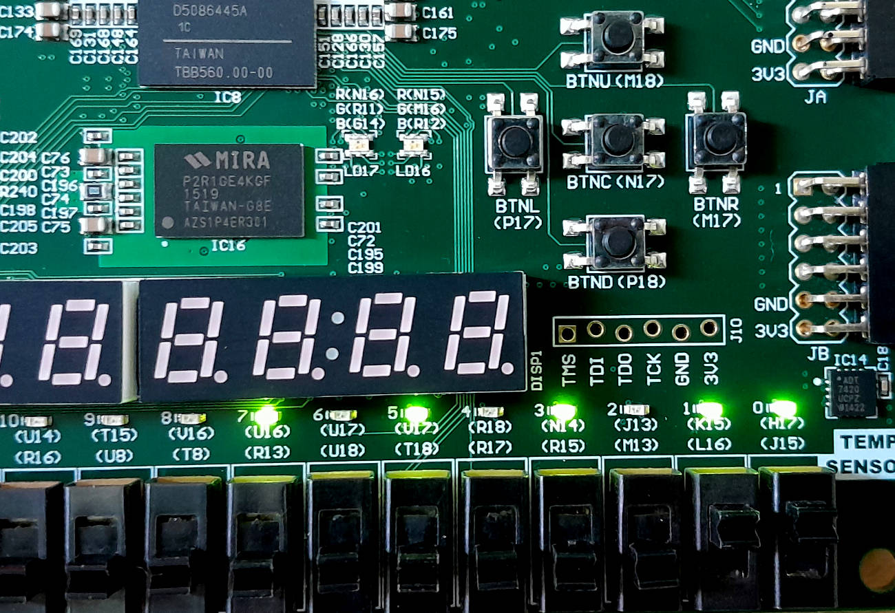
FPGA Implementation
Make connection of system clock to clock pin in top module. Connect reset and stop to switches and output to LEDs. Generate bitstream and program the FPGA board. Keep reset to logic 1 and stop to logic 0, you will observe output is incrementing in each second. Change the state of switches and observe the output.