
Data Flow Modeling In Verilog
Data Flow Modeling is the 3rd level of abstraction in Verilog.
Keywords Required
- assign
- wire
In above keywords assign is known as continious assignment keyword. and using wire keyword we can declare internal connections.
Describe a hardware using these keyowrds
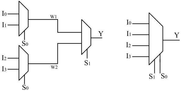
Let us describe a 4X1 MUX using data flow modeling. Write the boolean expression and make a logic circuit diagram.
Boolean Expression
$$Y = \bar S_1 \bar S_0 I_0 + \bar S_1 S_0 I_1 + S_1 \bar S_0 I_2 + S_1 S_0 I3$$
Circuit Diagram
For little deeper understanding
Let's make 4X1 MUX using 2X1 MUX
Let's make 4X1 MUX using 2X1 MUX
First, create a module and define input output ports. Declare internal connection using wire keyword.
By usign assign statement write the boolean expression in a single line. Thats it 😀
/*
  Module     : mux4x1_df.v
  Created By : circuitfever.com
  Create on  : 22-01-2023
*/
module mux4x1(
    input I0,I1,I2,I3,S0,S1,
    output Y
    );

wire w1,w2;

assign w1 = (~S0 & I0) | (S0 & I1);
assign w2 = (~S0 & I2) | (S0 & I3);
assign Y = (~S1 & w1) | (S1 & w2);

endmodule
0 Likes