
Full Wave Rectifier
A rectifier is an electronic circuit which can convert an AC voltage into DC voltage. In half-wave rectifier, only a positive cycle is rectified and the negative cycle is attenuated. A circuit, which can rectify both positive and negative cycle is known as a full-wave rectifier.
For full-wave rectification, there are two commonly used circuits which are given by:
- Centre-tapped full-wave rectifier
- Full-wave bridge rectifier
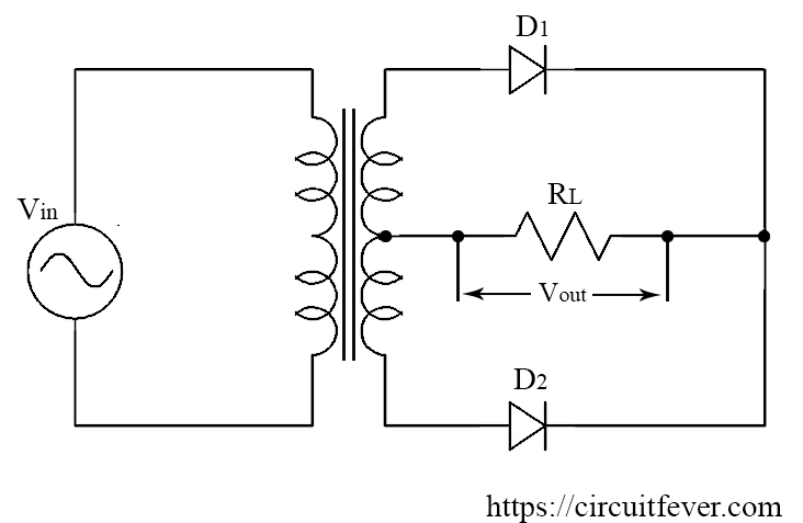
Centre-tapped full-wave rectifier
In this rectifier, we use a centre-tapped transformer to rectify both the positive and negative cycle of the AC voltage. That is why this circuit named centre-tapped full-wave rectifier. This circuit consists of two diodes and one load resistance that are connected such a way that both the cycle of AC voltage can be rectified.
Working
By using a centre tapped transformer, we are dividing input voltage into two parts.
During the positive cycle of the input voltage, potential at the input terminal of diode "D1" is high. This makes the diode "D1" in forward biased. Hence the diode "D1" conducts current through the load resistor. Similarly, the potential at the input terminal of the diode "D2" is less and this makes the diode "D2" in reverse biased and it does not conduct current.
During the negative half cycle of the input voltage, potential at the input terminal of diode "D1" less. This makes the diode "D1" in reverse biased and it does not conduct current. Similarly, the potential at the input terminal of the diode "D2" is high and this makes the diode "D2" in forward biased and hence the diode D1 conducts current through the load resistor.
In both cases, the current flows through the load resistor are in the same direction. Since the output is always positive hence this circuit is known as a full-wave rectifier.
Advantages
- Efficiency is high as compared to a half-wave rectifier
- Less distortion as compared to a half-wave rectifier
Disadvantages
- Locating the centre tap of the secondary winding is difficult
- The diodes must have high peak inverse voltage
Full-wave bridge rectifier:
This is the most popular and most widely used circuit for rectification of AC voltage because this circuit doesn't require any transformer.
The arrangement of diodes in the bridge network such that both positive and negative cycles of the input voltage can be rectified is known as a bridge rectifier.
In full-wave centre tapped transformer rectifier, we need a centre tapped transformer. By using an additional two diodes in full-wave rectifier we can eliminate the need of centre-tapped transformer as it is difficult to locate centre-tap on the transformer's secondary winding.
Circuit diagram for bridge rectifier is shown below
This rectifier circuit consists of four PN diode pointed towards one direction and one load resistor. This rectifier circuit conducts current during both positive and negative half cycle of the input voltage. This circuit is known as the full-wave bridge rectifier.
During the positive half cycle of the input voltage, diode "D2 and "D3" becomes in forward biased and start to conduct current or act as the closed switch and also "D1" and D4" becomes in reversed biased and act as the open switch (We have assumed that the diode is ideal). Current flows through the load resistor RL.
During the negative half cycle of input voltage diode " D2 and D3" becomes in forward biased and start to conduct current and also "D1 and D4" becomes reversed biased and act as open-circuited. Current flows through resistor "RL" in the same direction as of positive cycle.
The voltage across the load resistor "RL" is always positive for both positive and negative cycle of input voltage because the current is flowing through the load resistor in the same direction with the help of the bridge diode connection.
The output frequency of the full-wave bridge rectifier is equal to the twice of the input frequency. As shown in the above figure, the output voltage has two cycles in the time from 0 to T whereas input voltage has only one cycle for the time from 0 to T.
The input and output voltage waveform of full-wave rectifier:
Advantages of Bridge rectifier
- There is no need for a centre tapped transformer.
- The output voltage is twice for the same secondary voltage as compared to the full-wave rectifier
- Efficiency is high as compared to a half-wave rectifier