Getting Started With Arduino Uno
Arduino is a well-known name today in the field of embedded systems and the Internet of Things (IoT). The creator of Arduino created it with the motivation to make electronics accessible to everyone (even to people with non-engineering backgrounds). They provide simplified microcontroller hardware and software tools that people can easily use to program a microcontroller and build a creative electronic system (also known as an embedded system in technical terms).
The Arduino Uno is the simplest microcontroller board, designed by the creator of Arduino, and it was made open source. You can buy this board from their website arduino.cc. Since it is open source, you can purchase a copy at a very low cost, which functions similarly to the original Arduino Uno board. The low-cost board can be very useful for students or those who cannot afford the original board, which is costly for some students.
Broadly, building an embedded system is a two-step process: first, build the necessary hardware, which includes a microcontroller, and then develop embedded software to make the system work. In earlier days, it was not so easy to develop or learn embedded systems, thanks to the creator of Arduino, who made the entire process easier. Now, the process involves obtaining the Arduino board, installing the IDE, and developing the software.
Arduino Uno R3
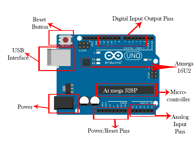
Arduino Uno R3 development board is an 8-bit microcontroller embedded in a single board. It looks similar to the picture shown below.

The Arduino R3 Board has:
- 12 input-output pins - These pins can be used to take digital inputs from the outside world and can be used to send digital output to the digital devices.
- Reset button - This button is used to reset the microcontroller.
- USB interface - It is used to connect the Arduino board from the host machine for download code from the host machine to the microcontroller.
- Power connection - It is used to connect the external power source to the board.
- Power/reset pins - These pins contain some power pins, ground pins, and reset pins. These pins can be used to power up the external devices that are connected to the board.
- Analog input pins - These pins can be used to take analog input from the external world. You can connect sensors to these pins to take analog inputs. Please note that these pins can't be used for analog output.
- Atmega328P microcontroller - This is the main microcontroller chip or IC. All the codes are written into this chip and executed by this chip itself.
- Atmega16U2 - This is another chip embedded on the board. It handles only the communication between the USB protocol and the microcontroller. It only translates the code from the USB protocol so that the microcontroller can understand that code. Also, if the host machine wants to take input from the microcontroller, it translates that code to the USB protocol.
- Additionally, the board has two pins Txd and Rxd which are used for serial communication. Also, the board has four LEDs (L built-in LED for output, TX, RX, and ON).
Arduino IDE
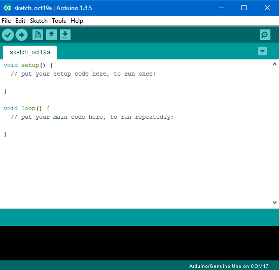
Arduino has its own integrated development environment (IDE). It is a software environment, you can write code there, compile your code and upload code in the board. You can download Arduino IDE from arduino.cc. After downloading the IDE, you can install it on your host machine laptop or computer. Arduino IDE looks like as below image.

Let's try some code to understand better
Project 1: Blinking LED. (For this example you don't need to connect external LED because the board itself has built-in LED L at the top left of the board below GND pin)
Step 1: Install the Arduino IDE to your host machine.
Step 2: Connect Arduino Board with the USB cable to your host machine.
Step 3: Write the following code to the IDE.
void setup(){
    pinMode(LED_BUILTIN, OUTPUT);
}

void loop(){
    digitalWrite(LED_BUILTIN, HIGH);
    delay(1000);
    digitalWrite(LED_BUILTIN, LOW);
    delay(1000);
}
Step 4: Click on the Upload button at the top left of the IDE. After uploading the code LED will start blinking.
Let's try to break the code
void setup()
The setup function will execute only ones after pressing the reset button or power the board. You can initialize input-output pins in this function.
pinMode(LED_BUILTIN, OUTPUT);
First of all, we need to define input-output pins. In this code, the output pin is LED_BUILTIN.
Most Arduinos have an onboard LED you can control. On the UNO, it is attached to digital pin 13. LED_BUILTIN is set to the correct LED pin.
It is set to OUTPUT so, LED_BUILTIN becomes output pin.
Please note that every statement must end with a semicolon ';'.
void loop()
The loop function runs over and over again forever.
digitalWrite(LED_BUILTIN, HIGH);
The digitalWrite statement is used to send the digital bit on the selected pin. HIGH for digital 1 and LOW for digital 0. In Arduino Uno HIGH is equal to 5V and LOW is equal to 0V. So, this statement means to send digital bit 1 at LED_BUILTIN to turn on the LED.
delay(1000);
This statement is used to provide the delay. Value is set to 1000 so, this will provide approximately 1 second of delay.
digitalWrite(LED_BUILTIN, LOW);
This statement is used to turn the LED off by making the voltage LOW.
Let's try another example for the same project i.e blinking led.
We want to turn on the led for half second and after that led will turn off for a second and this process will run over and over.
First of all, we need to define the output pin. As I mentioned earlier, in Arduino Uno built-in LED is connected to the pin 13. So, we define pin 13 as output. Let's do it.
Write the following line before void setup()int led = 13;
We take a variable led which is an integer and the value of the integer is 13.
void setup(){
    pinMode(led, OUTPUT);
}
In this statement, we initilize the pin led as OUTPUT.
void loop(){
    digitalWrite(led, HIGH);   //trun on the led
    delay(500);                //delay of half second
    digitalWrite(led, LOW);    //turn off the led
    delay(1000);               //delay of 1 second
}
