Half Adder Verilog Code
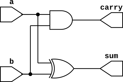
Half adder is a combinational circuit which computer binary addition of two binary inputs. It is one of the basic combinational circuit in which we have combination of two gates (ex-or gate, and gate). The truth table of half adder is given below and we can write boolean expression for half adder as follows $$sum = a\oplus b$$ $$carry = ab$$
Half Adder Truth Table
Input a |
Input b |
Output sum |
Output carry |
|
0 |
0 |
0 |
0 |
|
0 |
1 |
1 |
0 |
|
1 |
0 |
1 |
0 |
|
1 |
1 |
0 |
1 |
Half Adder Verilog Code
Half adder has two inputs (a,b) and two outputs (sum,carry). First, create a module with a module name half_adder_s as given below.
//half adder using structural modeling
module half_adder_s ();

endmodule
Now create input output port list.
//half adder using structural modeling
module half_adder_s (
    input a,b,
    output sum,carry
);

endmodule
Now desciribe the hardware inside the module. Sum is a ex-or b and carry is a and b. We can use any hardware modeling for describing a half adder. Below is the verilog code using structural modeling because we are using logic gate instantiation for descibing logic gates.
//half adder using structural modeling
module half_adder_s (
    input a,b,
    output sum,carry
);

xor(sum,a,b);
and(carry,a,b);

endmodule
Below is the Verilog code for half adder using data-flow modeling because we are using assign statement to assign a logic function to the output.
//half adder using data flow modeling
module half_adder_d (
    input a,b,
    output sum,carry
);

assign sum = a ^ b;
assign carry = a & b;

endmodule
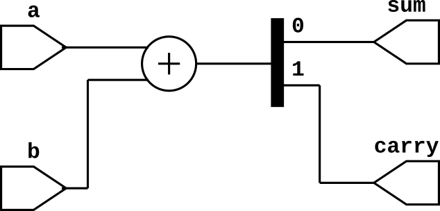
We can also use adder operator for creating half adder crcuit because half adder is basically addition of two binary inputs as given below.
//half adder using Verilog Operator
module half_adder_o (
    input a,b,
    output sum,carry
);

assign {carry,sum} = a+b;

endmodule
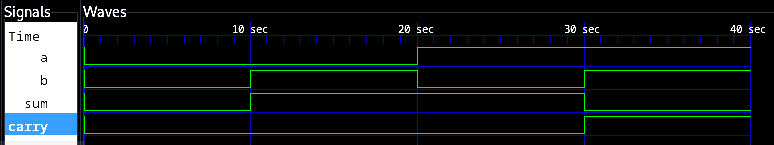
Half Adder Testbench
module half_adder_tb;
reg a,b;
wire sum,carry;

half_adder_s uut(a,b,sum,carry);

initial begin
a = 0; b = 0;
#10
b = 0; b = 1;
#10
a = 1; b = 0;
#10
b = 1; b = 1;
#10
$finish();
end

endmodule