
Half Wave Rectifier Explanation
We live in a world where almost every device works with DC voltage and power available at our home and offices are AC voltage. Devices like laptops, mobile phones, modern TVs, LED bulbs, tablets etc. doesn't work with AC voltage. AC voltage must be converted into DC voltage so that we can use our devices. So, a rectifier is a device which helps us to achieve this goal.
What is AC and DC voltage?
We know that the voltage is the potential difference between two points or wires.
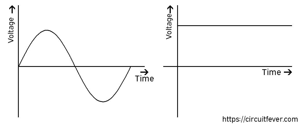
AC voltage is a two-directional voltage. It can be positive or negative at some time. The graph of AC voltage at our home is like a sinusoidal wave.
DC voltage is one-directional voltage. Either it can be positive or negative. Most of the time, we deal with a positive DC voltage.
Rectifier
A rectifier is an electronic circuit which converts AC voltage into DC voltage. Transformation of AC voltage into DC voltage is known as rectification. Designing a rectifier is a two-step process.
- Convert bidirectional voltage into a unidirectional voltage.
- Remove all the remaining AC components to get pure DC voltage.
Step 1
So, we don't require any negative voltage. We can convert bidirectional voltage to directional voltage by two methods:
- Remove all the negative voltage or
- Convert all negative voltage to positive voltage
If we are removing negative voltage, it is known as half-wave rectification because we are using only positive half a cycle.
We can design half-wave rectifier using a diode because a diode can eliminate negative voltage.
Half wave rectifier using a diode
We are considering that the diode is ideal. It means the diode behaves similar to closed switch when it is in forward biased and acts as an open switch when it is in reverse biased.
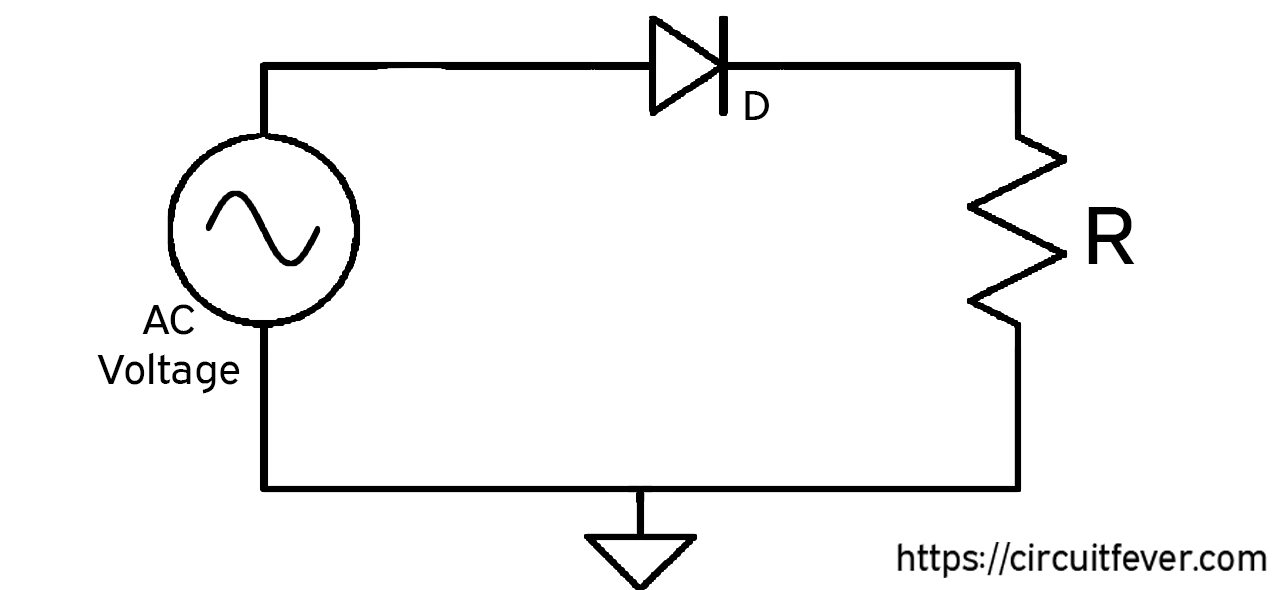
When we say a closed switch, it means that the resistance of the device is zero. Furthermore, an open switch means the resistance is infinite. Circuit Diagram of a half-wave rectifier is shown below:
How does this circuit work?
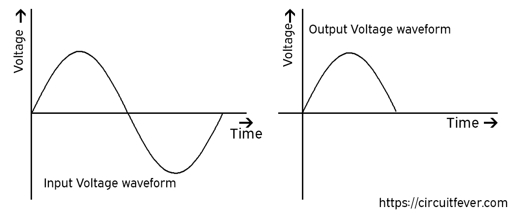
Let's consider the input voltage is like a sinusoidal wave.
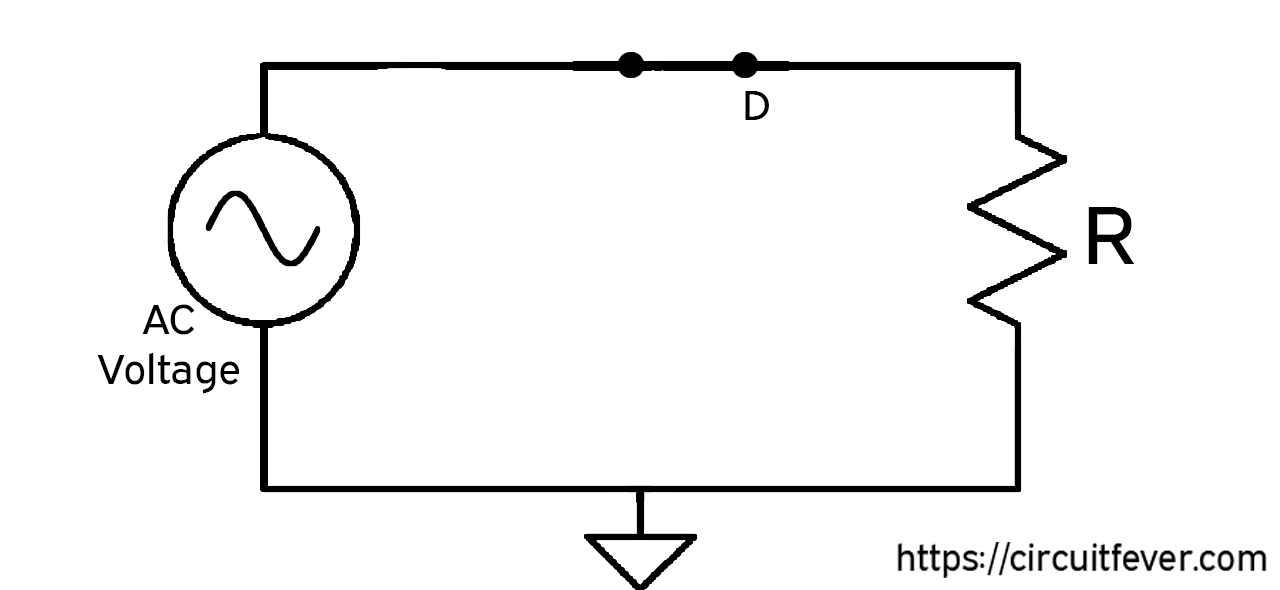
For the first half cycle, the voltage is increasing from zero to maximum and then decreasing from maximum to zero. In this period, we can see that the diode is in forward biased means it acts as a closed switch. At the output section, we have a resistor which is parallel to the input. The output will be the replica of input voltage because, in the parallel circuit, the voltage remains the same.
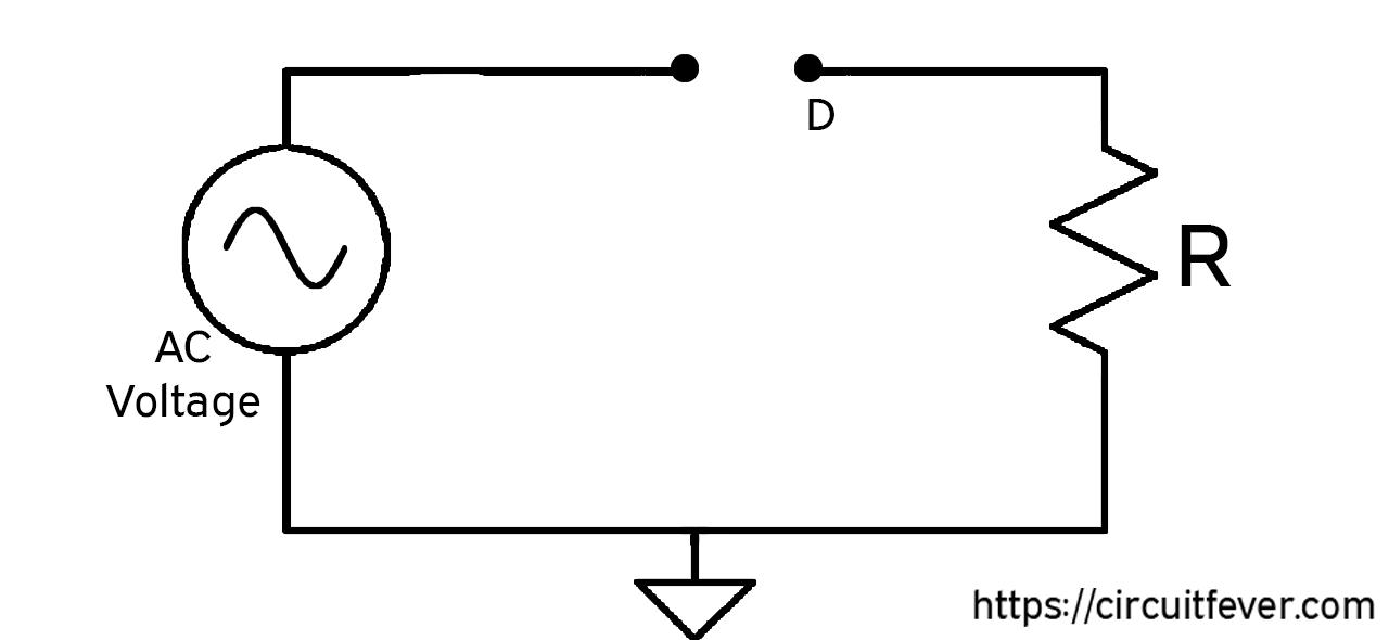
For the second half cycle, the voltage is decreasing from zero to a minimum and then increasing from minimum to zero. In this period, we can see that the diode is in reversed biased means it acts as an open switch. There will be no output because the circuit is open.
Step 2
So far we have just completed the first step towards rectifier design which is the conversion of bidirectional voltage to unidirectional voltage. We know, the DC voltage doesn't change with time. We can say that the output has some AC components. Filter circuit can remove those AC components. There are lots of filters like the RC filter and many more. We just required to connect filter at the output of the rectifier.
Conclusion
- It is low cost because only a diode and a resistor are required to design the rectifier.
- The output contains the AC component whose basic frequency is equal to the supply frequency and filtering is required to produce direct current.
- It can't be operated at high voltage because only one diode is used. The diode can easily be damaged at high voltage.