
FPGA Processing System - An Introduction
For this tutorial we require Xilinx Vivado 2022 and Vitis IDE 2022 and Zynq 7000 Development Board (Zybo)
Create New Vivado Project
Step 1
1. Create a new Vivado Project and while creating the project, choose part number correctly. For this totorial I am using Zybo. If you are using Zybo Z7, choose Zybo Z7-10 in Default Part.
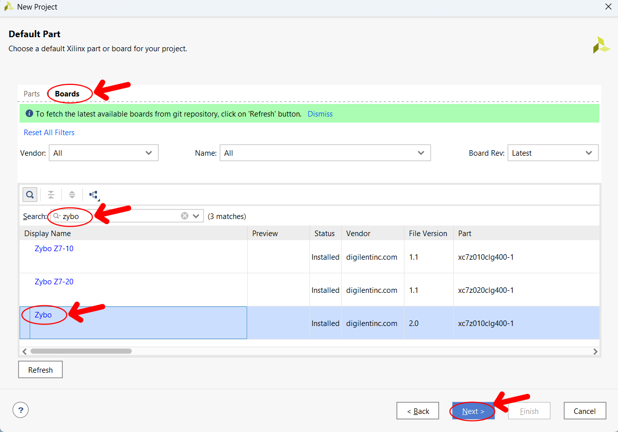
If board is not showing in default part then you have to install board files in Vivado. Click below button to find out how to install board files in Vivado
2. Create a new Design source and describe a full adder in it (Copy from the shared code)
3. Create a constrains file and add design constrains in it (Copy from the shared code)
4. Your design should have both full_adder module and design constrains (XDC File) before proceding to next step.
Step 2
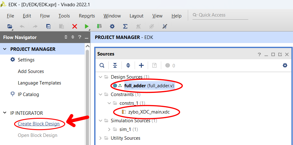
Click on Create Block Design
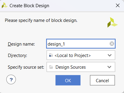
Type design name and Click on OK
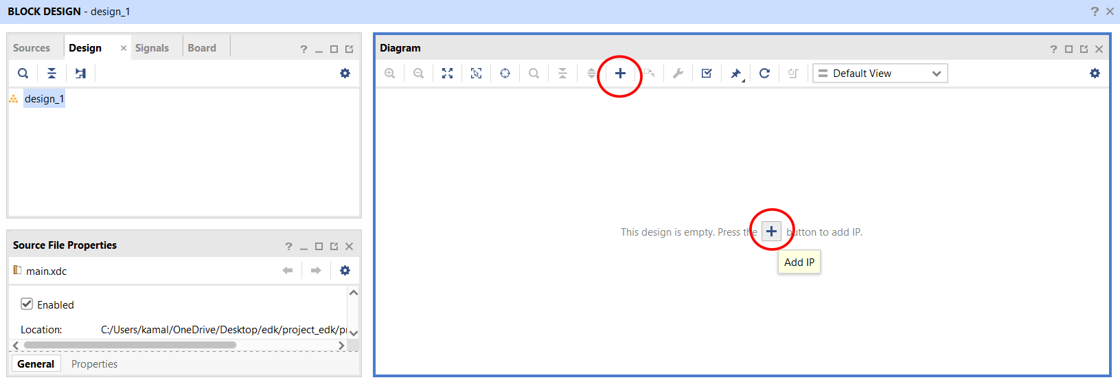
In Diagram window click on ADD IP button
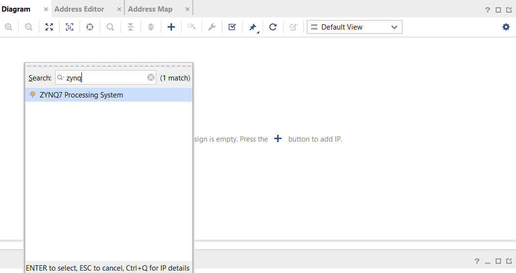
Search Zynq and double click to add this in your block design
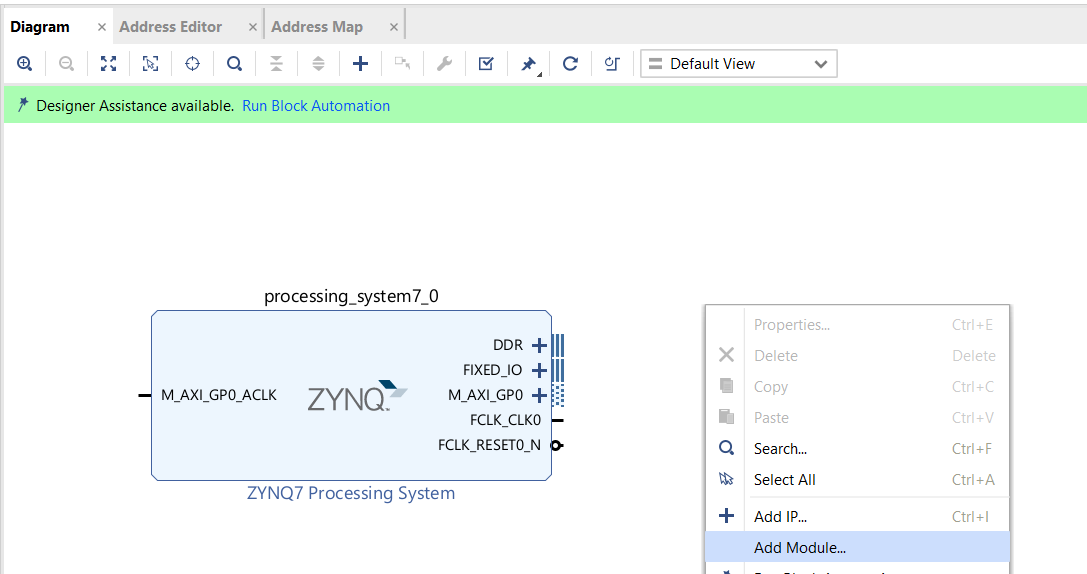
Right click on blank space and click on Add Module
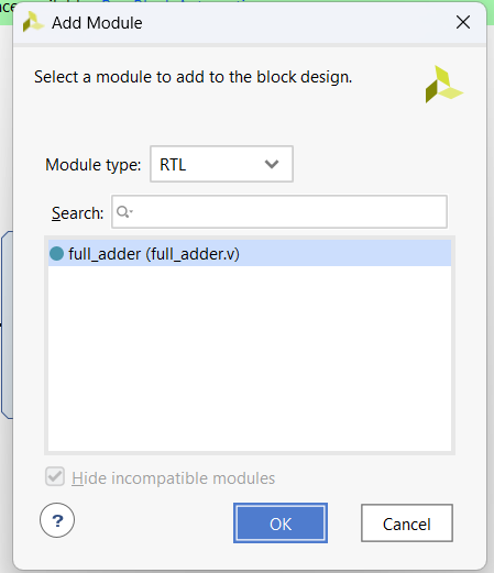
Select full_adder and click OK
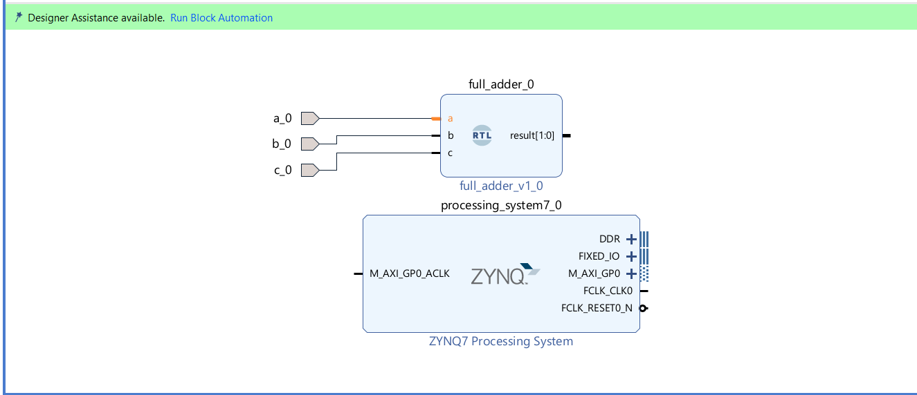
Right click on each terminal of full_adder and click Make External
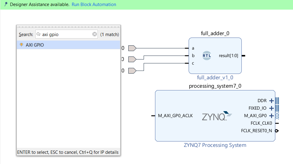
Click on Add IP and add AXI GPIO in your design
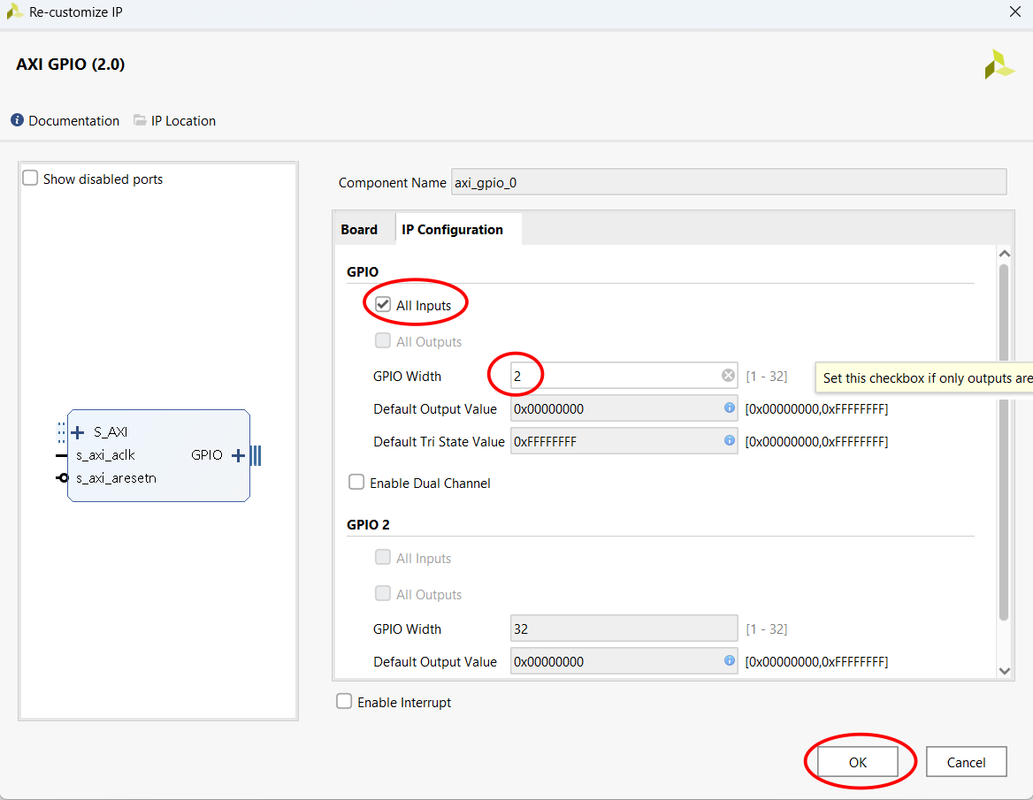
Double click on AXI GPIO and configure AXI GPIO as shown above
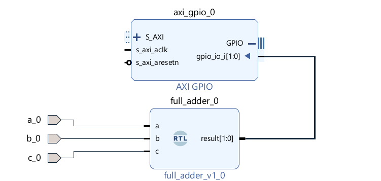
Make Connection between AXI GPIO and full_adder
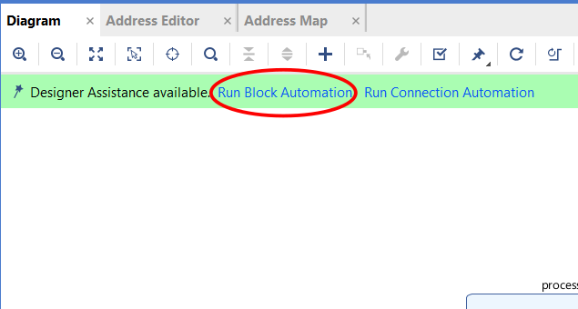
click on Run Block Automation
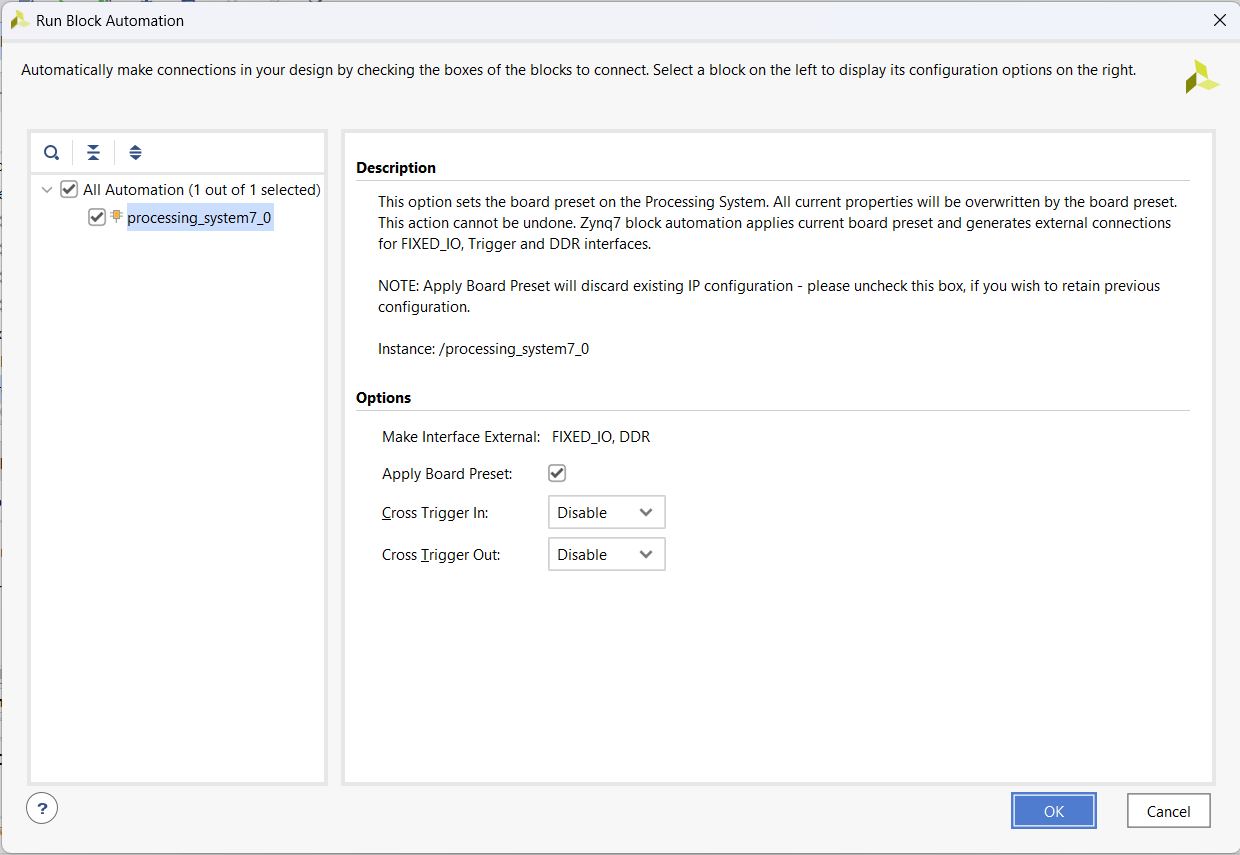
Click OK
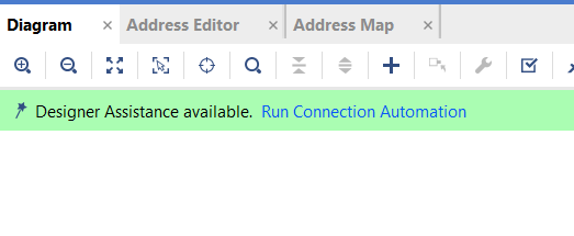
click on Run Connection Automation
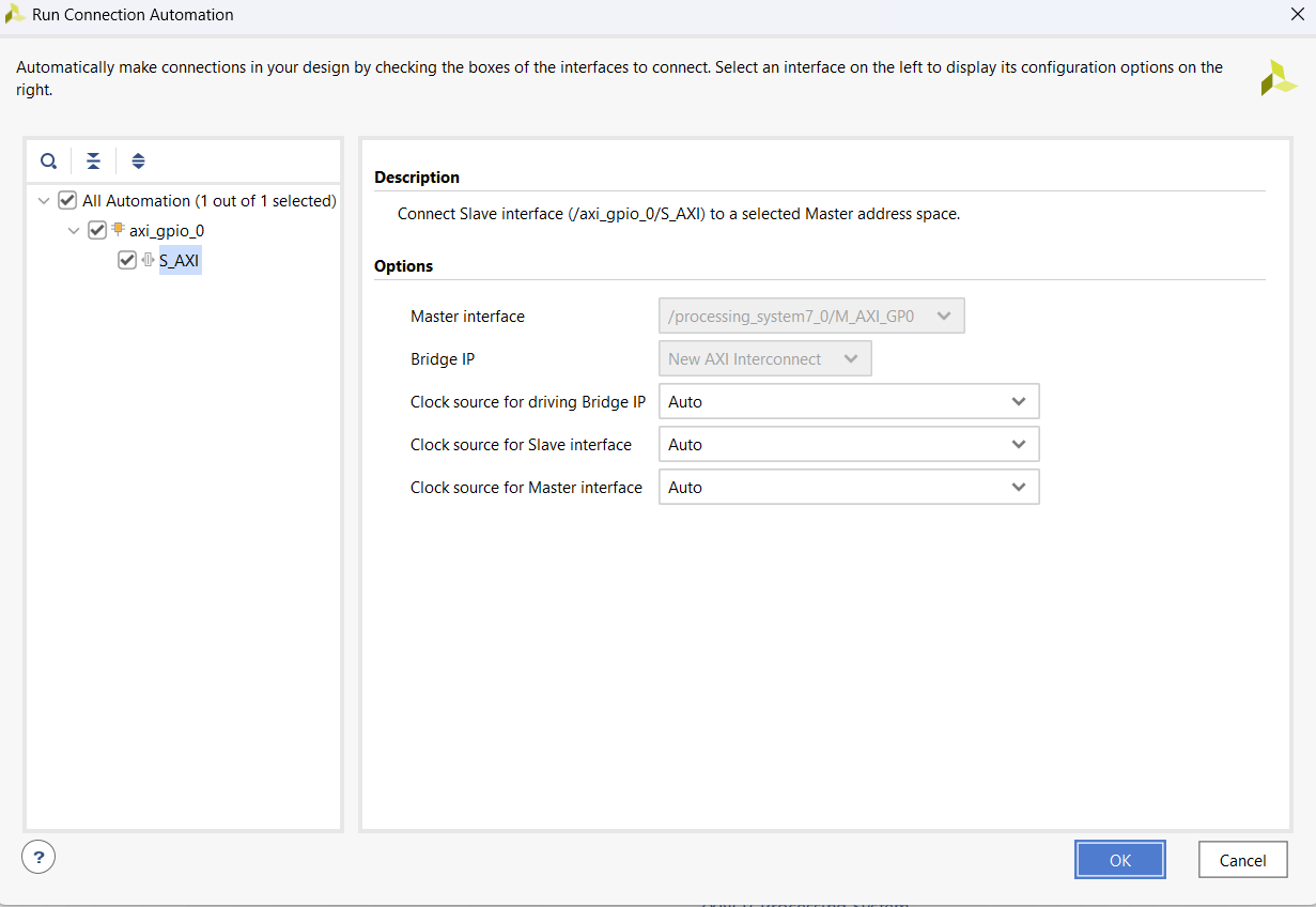
click on OK
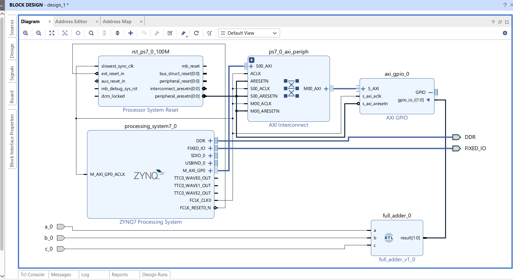
Your block diagram will look like this
Step 3
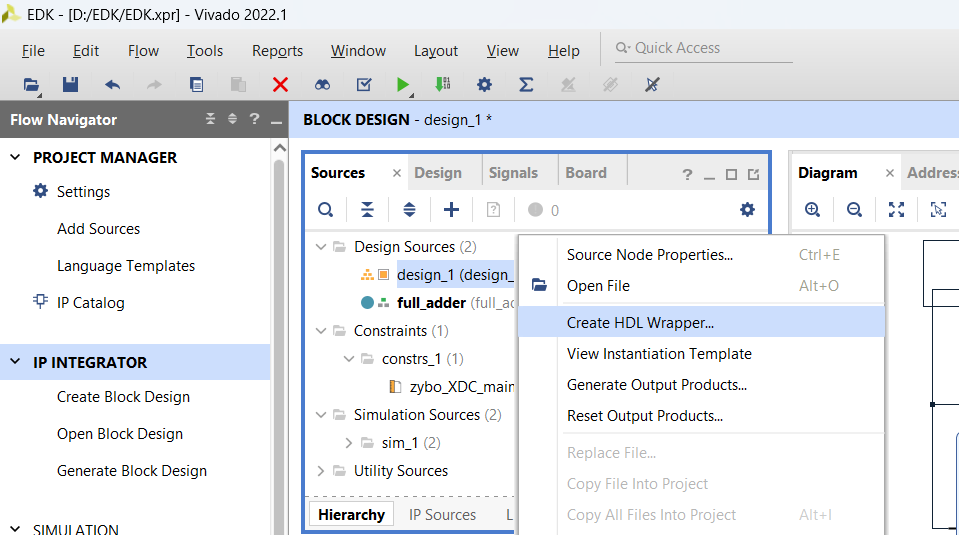
Go to source, right click on design_1 and click Create HDL Wrapper
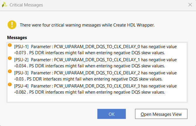
If you get warnings, click OK
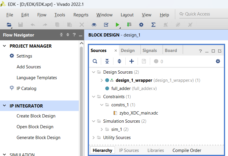
Make design_1_wrapper in top and click on Generate Bitstream
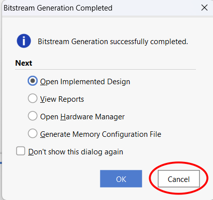
After Bitstream generation is completed click on Cancel
Step 4
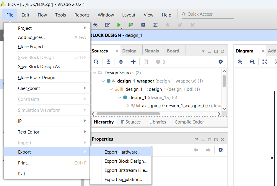
Click on File,Export ,Export Hardware
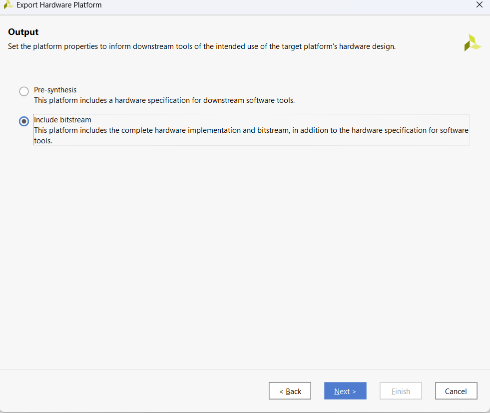
Click Next and select Include Bitstream
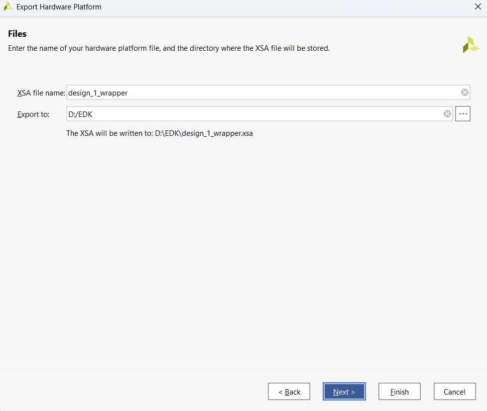
Save XSA file in your project directory
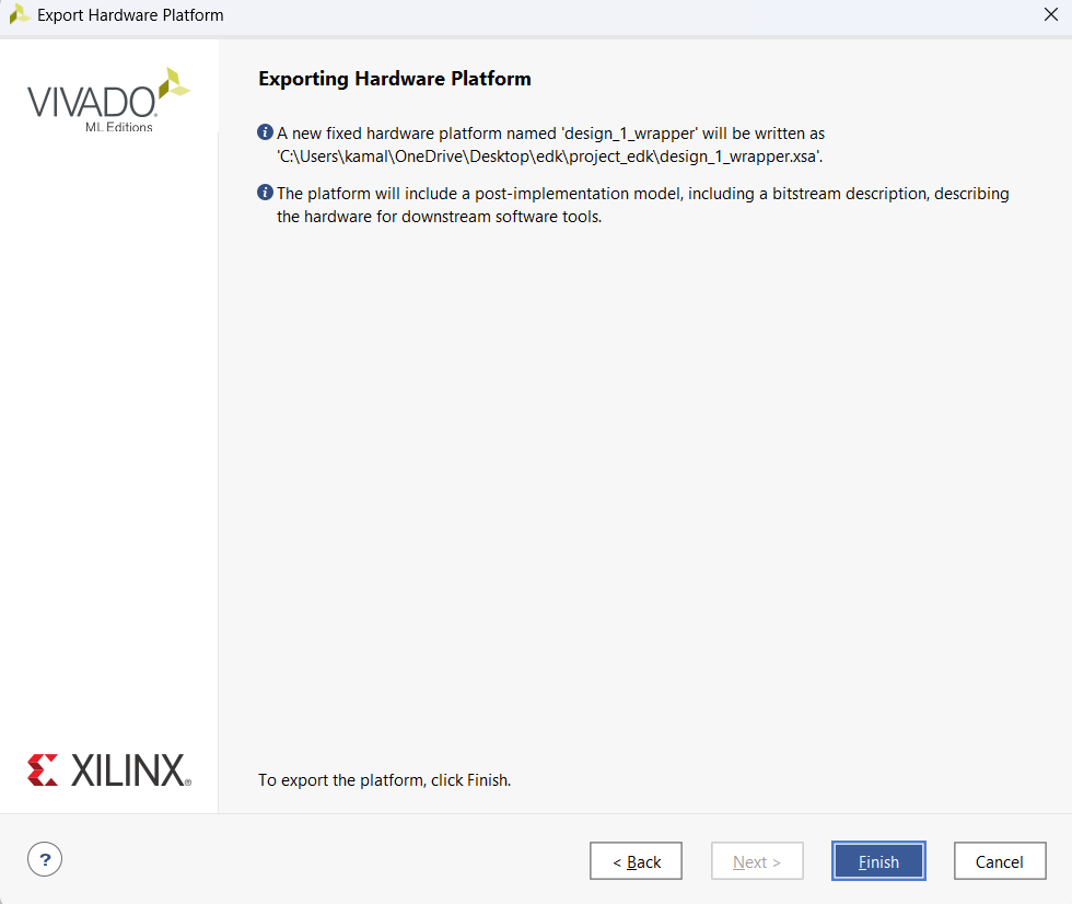
Click Finish
Step 5
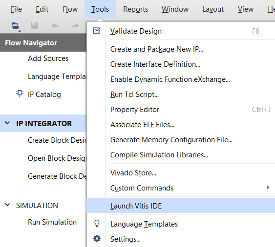
Click on Tools and click Launch Vitis IDE
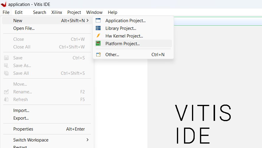
Click on File, New and Platform Project
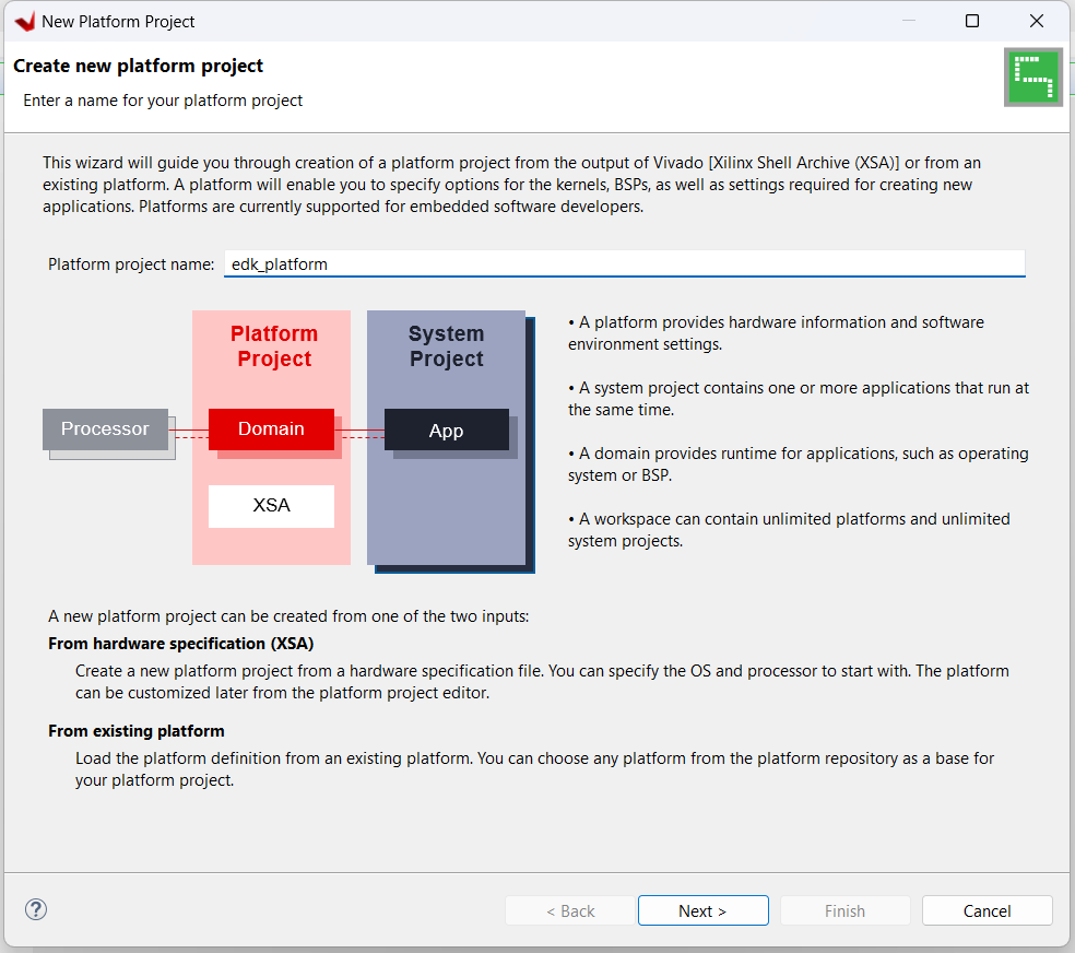
Type project name and click Next
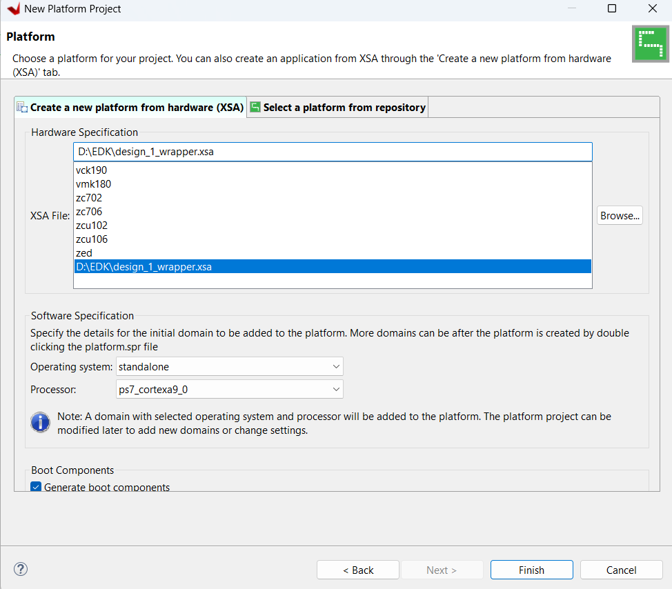
Click on Browse and choose exported XSA file (Export Hardware)
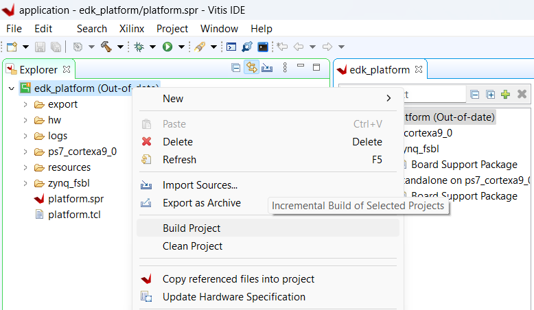
After creating the Platform Project it will look like this. Right click on Platform project and click Build Project
After finishing the Project Build
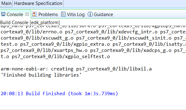
Step 6
Check in console window. When it shows Build Finished, go to next part
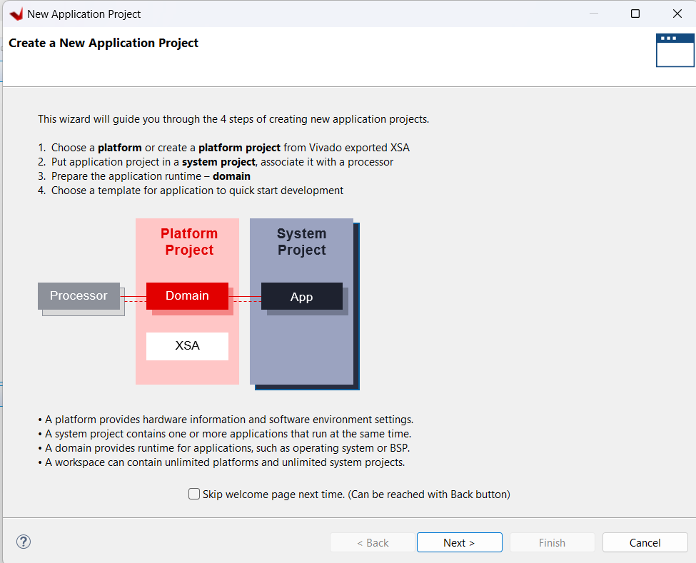
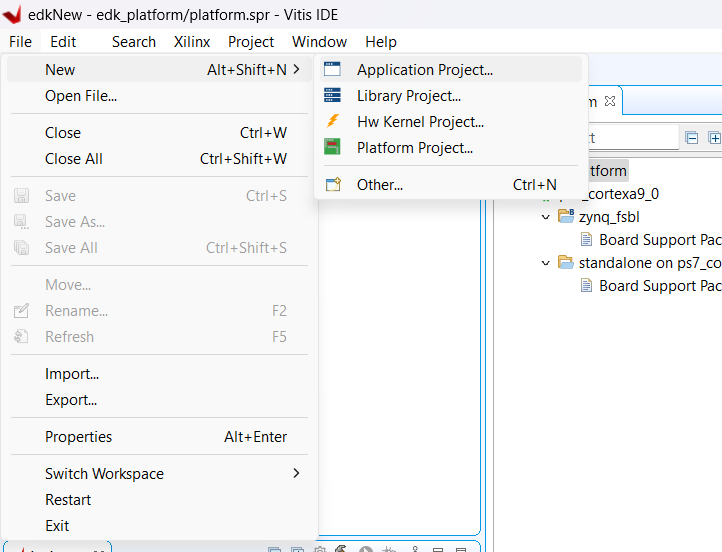
Click on File, New, Application Project
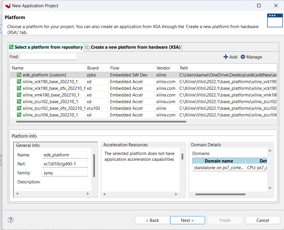
Choose Platform Project that we have created and click Next
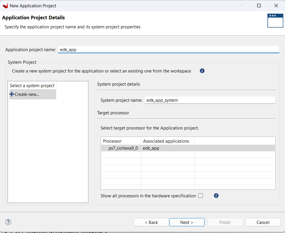
Type application name and click Next

Click Next
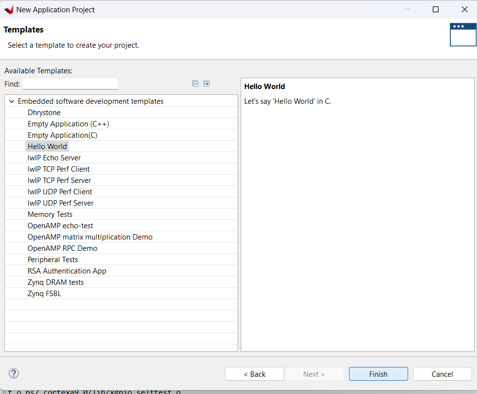
Choose Hello World Template and click Finish
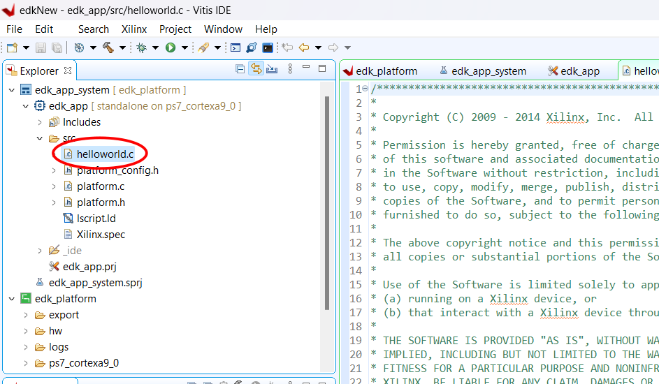
Expand Application project and modify helloworld.c (Copy Shared Code)
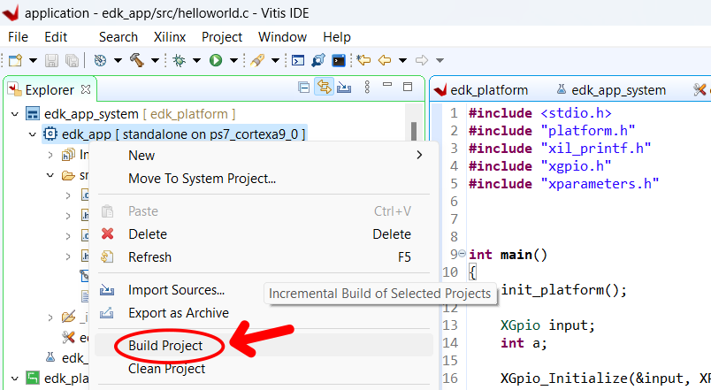
Right click on application project and click Build Project
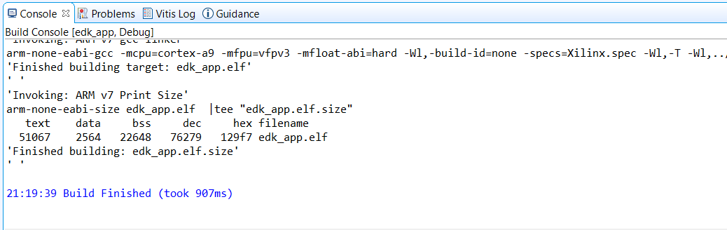
Check Console Window
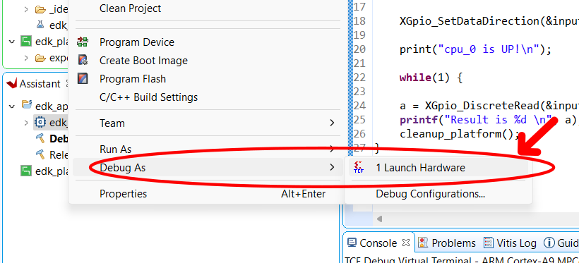
When building is done,Connect the FPGA Board and turn it on. right click on application project, Debug as, Launch Hardware
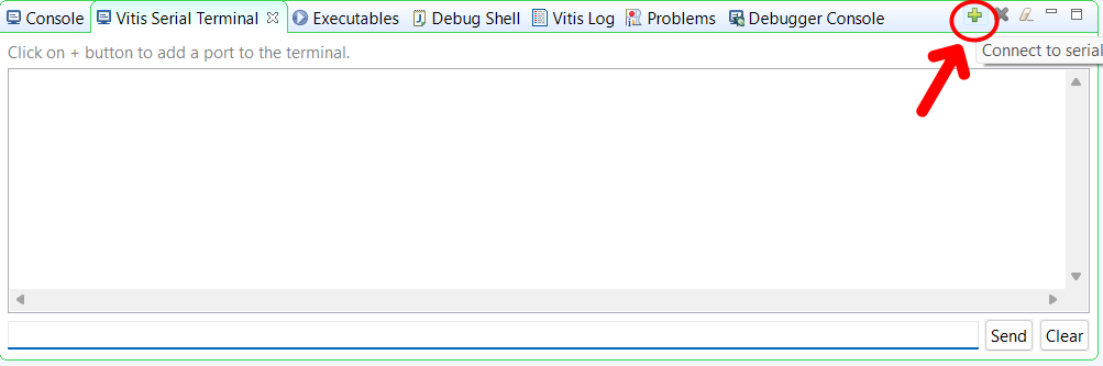
Click on Vitis Serial terminal
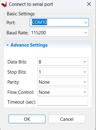
Choose COM PORT and Baud Rate and click OK
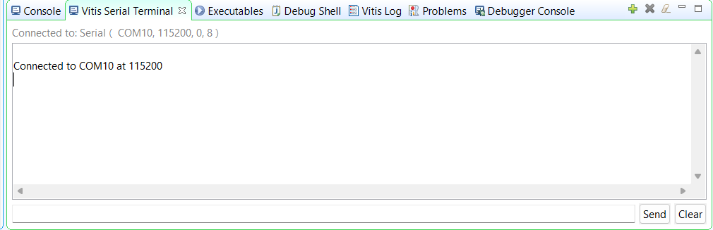
When UART is connected
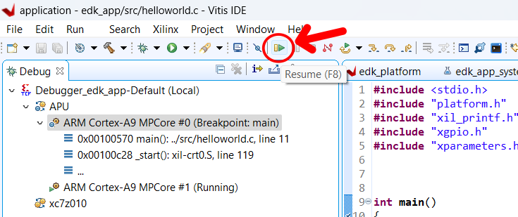
Now Click this Resume button
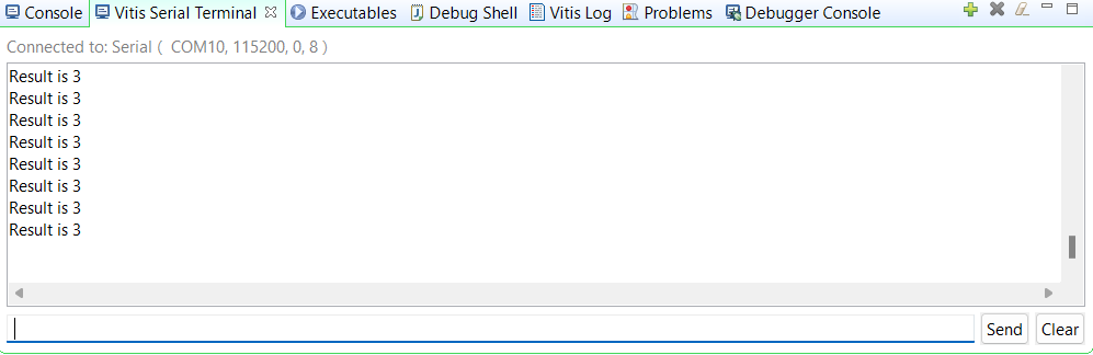
Otuput will be start showing on Vitis Serial Terminal