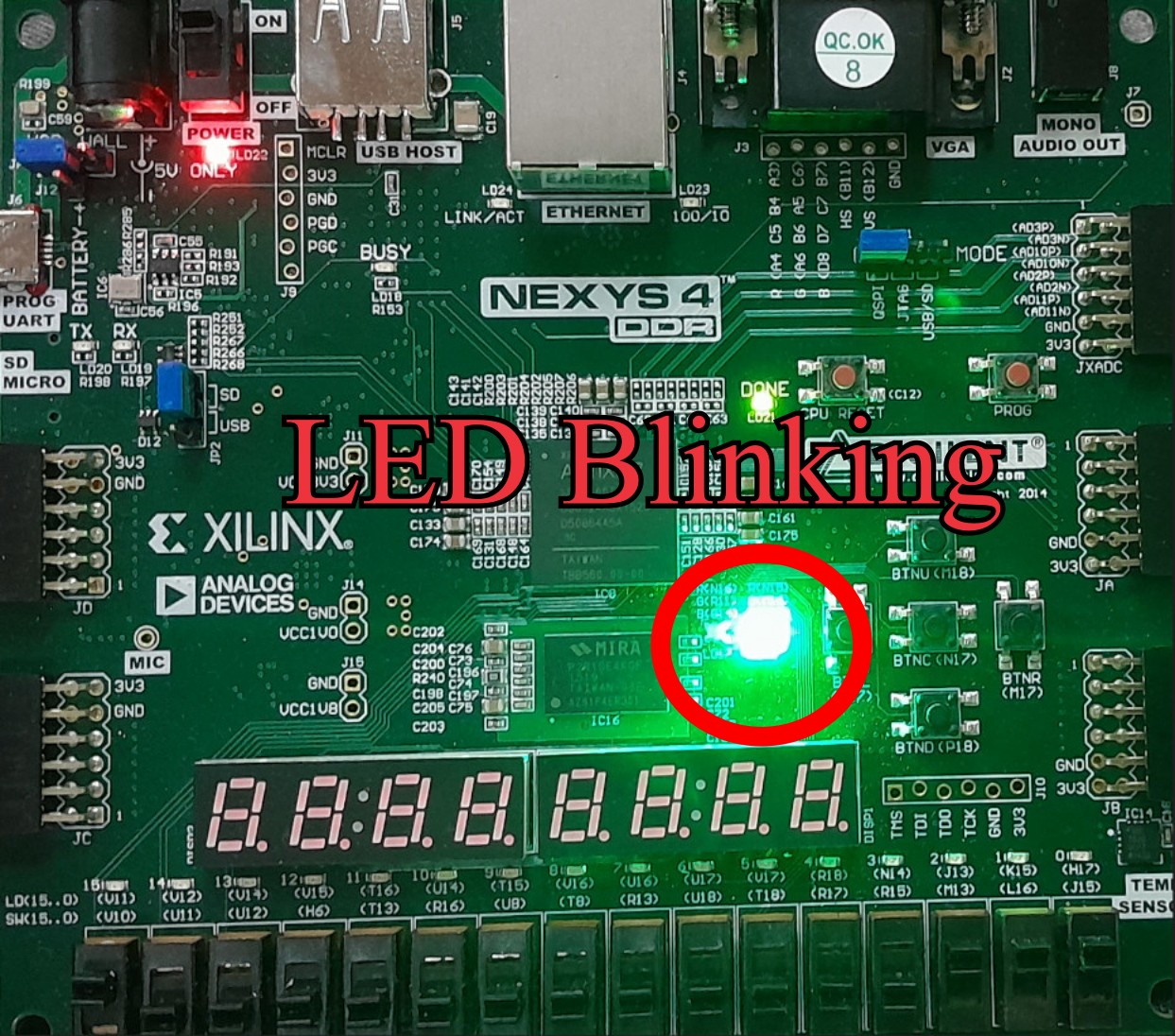
LED Blinking In FPGA using Verilog
When we start learning something, we start with a very basic things like if we are learning a programming language, we start with a Hello World! program. When we start learning something on hardware, we start with a LED blinking project. Like while learning Arduino for the first time, we start with a LED blinking program. In this tutorial we'll try to make out similar to Hello World! in Arduino (LED blinking) on FPGA.
What we require?
- A FPGA Board
- A Synthesis tool (Vivado)
- USB Cable
How to make?
You may know that if we want to make LED blinking project, we require a timing circuit or something which can give us the timing operation.
If you make same project in a hardware, we require a RC timing circuit or IC 555 timer. These circuit generates a timing waveform and we can connect the output of the timing circuit.
If you are making same project in a microcontroller like Arduino UNO, there we need a time delay function. We can use that delay function for time delay and then toggle the output of the output port. The output port is connected to the onboard LED or external LED and it blinks.
Let's talk about FPGA board
If we want some timing function, we can use clock. Every FPGA board has a system clock and the clock frequency varies from board to board. For example Digilent Nexys 4 DDR FPGA board has system clock of 100MHz.
We can't connect directly connect clock pin to the LED because we'll not be able to see the change of the clock output because 100MHz is a very high frequency. We need something which can generate delay. There are different methods to generate delay in digital circuit but we'll use timer for generating a delay.
Counter as a delay
We can make a counter and use that counter as a timer. Counter will count each clock cycle and with the use of a comparator, we make a timer. When certain value reaches in the counter, it will reset the counter or we can say that time is up. When time is up, we will toggle the output which is connected to the LED. Basically the value which resets the counter is the delay.
Verilog Description
The complete Verilog Code for LED blinking is given below. The code has a counter, comparator for time up operation and a register which output is toggles when time is up or certain value reaches in the counter.
module led_blink(
    input clk,
    output reg led
    );

reg [31:0]count;

always @(posedge clk) begin

if(count == 99999999) begin //Time is up
    count <= 0;             //Reset count register
    led <= ~led;            //Toggle led (in each second)
end else begin
    count <= count + 1;     //Counts 100MHz clock
    end

end

endmodule
The verilog has one input for feeding clock and one output register for LED output. The 32-bit register for counting the clock cycle. We are giving 100MHz clock to our design and 32-bit register is enough for counting 100 mega clock pulse. If clock frequency is 100MHz then counting this will require 1 second of time. This is how we are generating our delay function.
The circuit works at each and every positive edge of the clock and in each clock counter value is incremented by 1. when counter reaches 99999999 count, next clock pulse resets the counter to 0 (which means time is up). When time is up, counter resets to 0 and led register toggles. You can change the value of comparator and change the dealy.
Constraints File
In this file we make connection between the hardware available in FPGA board and our design. The board I am using has 100MHz of clock at pin E3 and Green LED at pin M16.
set_property -dict { PACKAGE_PIN E3    IOSTANDARD LVCMOS33 } [get_ports { clk }];
set_property -dict { PACKAGE_PIN M16   IOSTANDARD LVCMOS33 } [get_ports { led }];
FPGA Implementation
When everything is ready, synthesize the Verilog code and then implement the design. After the implementation, generate the bitstream file. Connect the FPGA board with the PC and program the FPGA board. You'll see LED is changing it's state in each second.