Logic Gates Verilog Code
Logic gates are the building block of digital circuit and system. We can make any digital circuit using logic gates. The are three basic logic gates AND, OR and NOT gate, two universal gate NAND and NOR and two other logic gates Ex-OR and EX-NOR. In this post, how to write Verilog code for logic gates is discussed.
There are three Verilog codes for each logic gate, you can use any one code.
NOT Gate
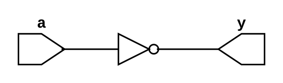
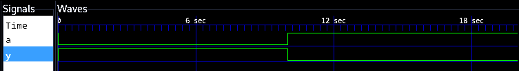
NOT gate has one input and one output and both are complement of each other. If input is 1 output is 0 and vice versa. The truth table of NOT gate is given below and we can write bolean expression of NOT gate as $$y = \overline a \text{ or } y = a'$$ $$\text{Where a is input and y is output}$$
NOT Gate Truth Table
Input a |
Output y |
|
0 |
1 |
|
1 |
0 |
NOT Gate Verilog Code
//NOT gate using Structural modeling
module not_gate_s(a,y);
input a;
output y;

not(y,a);

endmodule
//NOT gate using data flow modeling
module not_gate_d(a,y);
input a;
output y;

assign y = ~a;

endmodule
//NOT gate using behavioural modeling
module not_gate_b(a,y);
input a;
output reg y;

always @ (a)
y = ~a;

endmodule
NOT Gate Testbench
module not_gate_tb;
reg a;
wire y;

not_gate_s uut(a,y);

initial begin
a = 0;
#10
b = 1;
#10
$finish();
end

endmodule
AND Gate
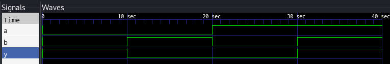
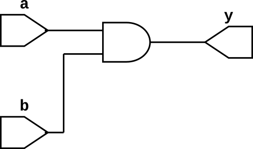
AND gate has many inputs (it can be two or more than two inputs) and one output. Output of the AND gate is 1 if and only if all of the inputs are 1. The truth table of 2-input AND gate is given below and we can write boolean expression for AND gate as follows $$y = ab \text{ or } y = a.b$$
AND Gate Truth Table
Input a |
Input b |
Output y |
|
0 |
0 |
0 |
|
0 |
1 |
0 |
|
1 |
0 |
0 |
|
1 |
1 |
1 |
AND Gate Verilog Code
//AND gate using Structural modeling
module and_gate_s(a,b,y);
input a,b;
output y;

and(y,a,b);

endmodule
//AND gate using data flow modeling
module and_gate_d(a,b,y);
input a,b;
output y;

assign y = a & b;

endmodule
//AND gate using behavioural modeling
module AND_gate_b(a,b,y);
input a,b;
output y;

always @ (a,b)
y = a & b;

endmodule
AND Gate Testbench
module and_gate_tb;
reg a,b;
wire y;

and_gate_s uut(a,b,y);

initial begin
a = 0; b = 0;
#10
b = 0; b = 1;
#10
a = 1; b = 0;
#10
b = 1; b = 1;
#10
$finish();
end

endmodule
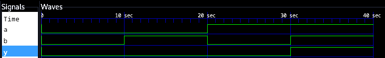
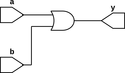
OR Gate
OR gate has many inputs (it can be two or more than two inputs) and one output. Output of the OR gate is 1 if one or more than one inputs are 1. The truth table of 2-input OR gate is given below and we can write boolean expression for OR gate as follows $$y = a + b$$
OR Gate Truth Table
Input a |
Input b |
Output y |
|
0 |
0 |
0 |
|
0 |
1 |
1 |
|
1 |
0 |
1 |
|
1 |
1 |
1 |
OR Gate Verilog Code
//OR gate using Structural modeling
module or_gate_s(a,b,y);
input a,b;
output y;

or(y,a,b);

endmodule
//OR gate using data flow modeling
module or_gate_d(a,b,y);
input a,b;
output y;

assign y = a | b;

endmodule
//Not gate using behavioural modeling
module or_gate_b(a,b,y);
input a;
output y;

always @ (a,b)
y = a | b;

endmodule
OR Gate Testbench
module or_gate_tb;
reg a,b;
wire y;

or_gate_s uut(a,b,y);

initial begin
a = 0; b = 0;
#10
b = 0; b = 1;
#10
a = 1; b = 0;
#10
b = 1; b = 1;
#10
$finish();
end

endmodule
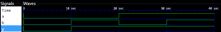
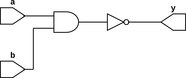
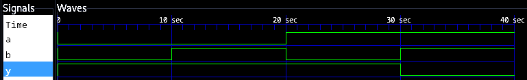
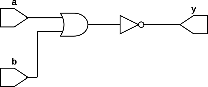
NAND Gate
NAND gate has many inputs (it can be two or more than two inputs) and one output. It is AND gate followed by NOT gate and output of the NAND gate is 0 if all inputs are 1 else it is 1. The truth table of 2-input NAND gate is given below and we can write boolean expression for OR gate as follows $$y = \overline{ab} \text{ or } \overline{a.b}$$
NAND Gate Truth Table
Input a |
Input b |
Output y |
|
0 |
0 |
1 |
|
0 |
1 |
1 |
|
1 |
0 |
1 |
|
1 |
1 |
0 |
NAND Gate Verilog Code
//NAND gate using Structural modeling
module nand_gate_s(a,b,y);
input a,b;
output y;

nand(y,a,b);

endmodule
//NAND gate using data flow modeling
module nand_gate_d(a,b,y);
input a,b;
output y;

assign y = ~(a & b);

endmodule
//NAND gate using behavioural modeling
module nand_gate_b(a,b,y);
input a;
output reg y;

always @ (a,b)
y = ~(a & b);

endmodule
NAND Gate Testbench
module nand_gate_tb;
reg a,b;
wire y;

nand_gate_s uut(a,b,y);

initial begin
a = 0; b = 0;
#10
b = 0; b = 1;
#10
a = 1; b = 0;
#10
b = 1; b = 1;
#10
$finish();
end

endmodule
NOR Gate
NOR gate has many inputs (it can be two or more than two inputs) and one output. It is NOR gate followed by NOT gate and output of the NOR gate is 1 if all inputs are 0 else it is 1. The truth table of 2-input NAND gate is given below and we can write boolean expression for OR gate as follows $$y = \overline{a+b}$$
NOR Gate Truth Table
Input a |
Input b |
Output y |
|
0 |
0 |
1 |
|
0 |
1 |
0 |
|
1 |
0 |
0 |
|
1 |
1 |
0 |
NOR Gate Verilog Code
//NOR gate using Structural modeling
module nor_gate_s(a,b,y);
input a,b;
output y;

nor(y,a,b);

endmodule
//NOR gate using data flow modeling
module nor_gate_d(a,b,y);
input a,b;
output y;

assign y = ~(a | b);

endmodule
//NOR gate using behavioural modeling
module nor_gate_b(a,b,y);
input a;
output reg y;

always @ (a,b)
y = ~(a | b);

endmodule
NOR Gate Testbench
module nor_gate_tb;
reg a,b;
wire y;

nor_gate_s uut(a,b,y);

initial begin
a = 0; b = 0;
#10
b = 0; b = 1;
#10
a = 1; b = 0;
#10
b = 1; b = 1;
#10
$finish();
end

endmodule
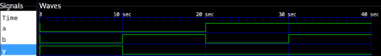
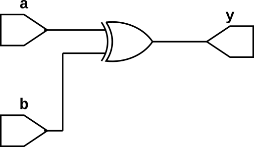
EX-OR Gate
EX-OR gate has many inputs (it can be two or more than two inputs) and one output. The output of EX-OR gate is 1 if odd number of inputs are 1 else it is 0. The truth table of 2-input EX-OR gate is given below and we can write boolean expression for OR gate as follows $$y = a\oplus b$$
EX-OR Gate Truth Table
Input a |
Input b |
Output y |
|
0 |
0 |
0 |
|
0 |
1 |
1 |
|
1 |
0 |
1 |
|
1 |
1 |
0 |
EX-OR Gate Verilog Code
//EX-OR gate using Structural modeling
module xor_gate_s(a,b,y);
input a,b;
output y;

xor(y,a,b);

endmodule
//EX-OR gate using data flow modeling
module xor_gate_d(a,b,y);
input a,b;
output y;

assign y = a ^ b;

endmodule
//EX-OR gate using behavioural modeling
module xor_gate_b(a,b,y);
input a;
output reg y;

always @ (a,b)
y = a ^ b;

endmodule
EX-OR Gate Testbench
module xor_gate_tb;
reg a,b;
wire y;

xor_gate_s uut(a,b,y);

initial begin
a = 0; b = 0;
#10
b = 0; b = 1;
#10
a = 1; b = 0;
#10
b = 1; b = 1;
#10
$finish();
end

endmodule
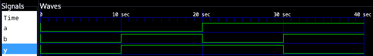
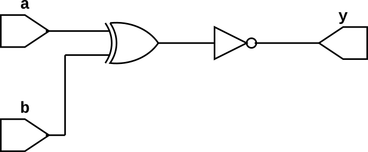
EX-NOR Gate
EX-NOR gate has many inputs (it can be two or more than two inputs) and one output. The output of EX-NOR gate is 1 if even number of inputs are 1 else it is 0. The truth table of 2-input EX-NOR gate is given below and we can write boolean expression for OR gate as follows $$y = \overline{a\oplus b}$$
EX-NOR Gate Truth Table
Input a |
Input b |
Output y |
|
0 |
0 |
1 |
|
0 |
1 |
0 |
|
1 |
0 |
0 |
|
1 |
1 |
1 |
EX-NOR Gate Verilog Code
//EX-NOR gate using Structural modeling
module xnor_gate_s(a,b,y);
input a,b;
output y;

xnor(y,a,b);

endmodule
//EX-NOR gate using data flow modeling
module xnor_gate_d(a,b,y);
input a,b;
output y;

assign y = ~(a ^ b);

endmodule
//EX-NOR gate using behavioural modeling
module xor_gate_b(a,b,y);
input a;
output reg y;

always @ (a,b)
y = ~(a ^ b);

endmodule
EX-OR Gate Testbench
module xnor_gate_tb;
reg a,b;
wire y;

xnor_gate_s uut(a,b,y);

initial begin
a = 0; b = 0;
#10
b = 0; b = 1;
#10
a = 1; b = 0;
#10
b = 1; b = 1;
#10
$finish();
end

endmodule