Module Instantiation In Verilog
Module is basic building block in Verilog where we can describe any hardware block. When design is very big or complex it is not easy to describe entire hardware block in a module. Istead of describing entire hardware in a single modlue, we can break the hardware into smaller modules and we can instantiate any module in out main module.
For example, we know that we can make full adder using two half adder. Even though we can describe a full adder in a module but we can also describe a half adder and instantiate half adder in main module to descrive a full adder.
It is not about how to make full adder using a half adder but it is about breaking a big or complex hadware module into smaller modules.
Module Instantiation
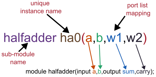
First of all your main module and sub-module should be in same path/folder. You can instntiate sub-module in main module, to do this write sub-module name inside the main module followed by a unique instance name. For example, if main module name is fulladder and sub-module name is halfadder then you can instantiate it as given below: halfadder ha0(port lists); Note: Module instantiation should be inside of module and endmodule
/*
  Module     : halfadder.v
  Created By : circuitfever.com
  Create on  : 07-11-2022
*/
module halfadder(
  input a,b,
  output sum,carry
);
xor(sum,a,b);   //sum = a exor b
and(carry,a,b); //carry = a and b
endmodule
Keep port list in same order
After unique instance name, inside of bracket you have to list the ports in the same order as it is declared in sub-module.For example, in above halfadder module, a and b are two inputs and sum and carry are two outputs and port declaration order is a,b,sum,carry.

As shown in above figure, a,b,w1 and w2 are ports and wire of main module. As per porr list order, a of main module will be mapped to a of sub-module halfadder, b of main module will be mapped to b of sub-module, w1 of main module will be mapped to sum of sub-module and so on.
Use defined port name (Same order not required)
In this method of module instantiation, we use port or wire name of both the module for mapping. For example if we want to map port a of main module to the port a of sub module, we write inside of the bracket of module instantiation: .sub_module_port_name(main_module_port_or_wire_name)
The complete full adder Verilog code is given below
In this Verilog code, both methods of module instantiation is demonstrated. Line 13 is using ordered port mapping and line 16 is port mapping using defined port or wire name.
/*
  Module     : fulladder.v
  Created By : circuitfever.com
  Create on  : 01-01-2023
*/
module fulladder(
    input a,b,cin,
    output SUM,carry
    );
wire w1,w2,w3;

//Port list mapping (list in order)
halfadder ha0(a,b,w1,w2);

//Post list mapping using name
halfadder ha1(.a(w1),.b(cin),.sum(SUM),.carry(w3));

or(carry,w2,w3);
endmodule

