Multiplexer In Digital Circuit
Multiplexer in digital circuit has many inputs (m) with only one output and it is denoted by m:1 MUX where m is the number of inputs. It selects only one input (one input is connected to the output) based on the select line. We can have 2X1 mux with 1 select line, 4X1 mux with 2 select line, 8x1 mux with 3 select lines, 16X1 mux with 4 select lines and so on.
2X1 MUX
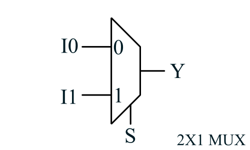
2X1 mux has two inputs, one output and one select line. The circuit diagram of 2X1 mux is shown below

Truth table of 2X1 mux
| S | I0 | I1 | Y |
|---|---|---|---|
| 0 | 0 | 0 | 0 |
| 0 | 0 | 1 | 0 |
| 0 | 1 | 0 | 1 |
| 0 | 1 | 1 | 1 |
| 1 | 0 | 0 | 0 |
| 1 | 0 | 1 | 1 |
| 1 | 1 | 0 | 0 |
| 1 | 1 | 1 | 1 |
Boolean Expression of 2X1 mux
We can write boolean expression for 2X1 MUX using above truth table. When select line S is logic 0, I0 is selected and when S is logic 1, I1 is selected.
$$Y = \overline S I0 + S I1 $$4X1 MUX
4X1 MUX has four inputs and only one output. We require 2 select line for realising 4X1 MUX S1 and S0. When both the select line is logic 0, I0 is selected. When S1 is logic 0 and S0 is logic 1, I1 is selected. When S1 is logic 1 and S0 is logic 0, I2 is selected and both the select line is logic 1, I3 is selected.

Boolean Expression of 4X1 mux
$$Y = \overline S1 \overline S0 I0 + \overline S1 S0 I1 + S1 \overline S0 I2 + S1 S0 I3$$4X1 MUX from 2X1 MUX
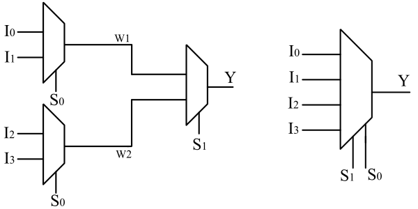
We can realise 4X1 MUX from 2X1 MUX. Observe the below truth table.
| S1 | S0 | Y |
|---|---|---|
| 0 | 0 | I0 |
| 0 | 1 | I1 |
| 1 | 0 | I2 |
| 1 | 1 | I3 |
We are dividing truth table into two parts using S1 select line and we are dividing S1 into two parts using S0 select line. With two 2X1 MUX and select line S0, we are selecting I0,I1 and I2,I3 and it is label as W1 and W2. Using S1 and 2X1 MUX we are selecting W1 and W2.
If S1 is logic 0, W1 is selected, and if S0 is logic 0, W1 is I0. If S0 is logic 1, W1 is I1. Similarlly, if S1 is logic 1, W2 is selected. If S0 is logic 0, W2 is I2 and if S0 is logic 1, W2 is I3.

