
Multiplexer Verilog Code
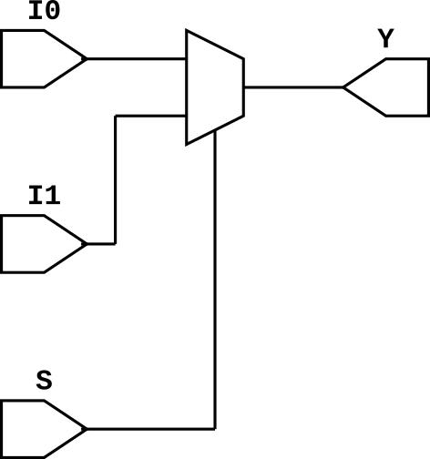
Multiplxer is an combinational circuit which has 2,4,8 and so on inputs with select line 1,2,3 and so on. Ouptut of the multiplexer is connected to the perticular input based on the select line. For example in 2X1 MUX, if select line is 0, first input is selected else second input is selected.
There are different ways to describe MUX in verilog. We can use gate level modeling, we can use data flow modeling, we can use ternary operator, we can use if else statement or we can use case statement. In this tutorial, we'll learn all of them.
2X1 Multiplexer Verilog Code
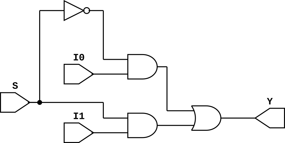
Let's start with basic 2X1 MUX in gate level modeling. It has two inputs, one select line and one output. The boolean expression for 2X1 is given as $$Y = \overline S .I0 + S.I2$$ For this, we require two AND gate, one OR gate and one NOT gate.
//2X1 MUX in gate level modeling
module mux_2x1_gl(
input I0,I1,S,
output Y);
wire sb,a,b;

not(sb,S);
and(a,sb,I0);
and(b,S,I1);
or(Y,a,b);

endmodule
We can also use data flow modeling for describing MUX which requires only one line of Verilog code inside of module block. Just write the boolean expression and it is done.
//2X1 MUX in gate level modeling
module mux_2x1_df(
input I0,I1,S,
output Y);

assign Y = (~S & I0)|(S & I1);

endmodule
Verilog has various operators and we can use ternary operator for describing a MUX. With one ternary operator, we can describe a 2X1 MUX and we can expand this operator for creating 4X1, 8X1 MUX and so on. In ternary operator, it checks for condition and if it is true, output is connected to first input else output is connected to second input. The example is given below.
module mux_2x1_dt(
input I0,I1,S,
output Y);

assign Y = S?I1:I0;

endmodule
We can use also use behavioural modeling for describing a MUX. For that, we can use if else statement or case statement. The examples are given below for 2X1 MUX.
module mux_2x1_bif(
input I0,I1,S,
output reg Y);

always @(*) begin
    if(S)
        Y = I1;
    else
        Y = I0;
end

endmodule
module mux_2x1_bcase(
input I0,I1,S,
output reg Y);

always @(*) begin
    case(Y)
    1'b0:
        Y = I0;
    1'b1:
        Y = I1;
    endcase
end

endmodule
Multiplexer Testbench
module mux_tb;
reg I0,I1,S;
wire Y;
mux_2x1_gl uut(I0,I1,S,Y);
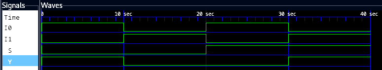
initial begin
S = 0; I0 = 1; I1 = 0;
#10
I0 = 0; I1 = 1;
#10
S = 1; I0 = 1; I1 = 0;
#10
I0 = 0; I1 = 1;
#10
$finish();
end
endmodule
4X1 Multiplexer Verilog Code
module mux_2x1_b(
input I0,I1,I2,I3,S0,S1,
output Y);

assign Y = S1?(S0?I1:I0):(S0?I3:I2);

endmodule
8X1 Multiplexer Verilog Code
module mux_2x1_b(
input I0,I1,I2,I3,I4,I5,I6,I7,S0,S1,S2,
output Y);

assign Y = S2?(S1?(S0?I1:I0):(S0?I3:I2)):(S1?(S0?I5:I4):(S0?I7:I6));

endmodule