
Inverting and Non-Inverting Operational Amplifier
An Operational Amplifier is a high gain direct-coupled amplifier and available in a single integrated circuit package. The operational amplifier is abbreviated to op-amp.
The operational amplifier can be used to amplify DC as well as AC input signals.
Originally operational amplifier was designed for performing mathematical operations such as addition, subtraction, multiplication, integration, differentiation.
In modern days op-amp can be used for a variety of applications such as amplification, active filters, digital to analog conversion, comparators, voltage buffer and much more.
Some features of op-amp
- An op-amp has very high input impedance and very low output impedance. For Ideal op-amp input impedance is infinite and output impedance is zero.
- It has a very high open-loop gain. For ideal op-amp, it is infinite.
- It consumes low power.
- It has a very high voltage gain. For ideal op-amp, it is infinite.
- It has a large bandwidth. For ideal op-amp, it is infinite so that any frequency signal can be amplified without attenuation.
- It has a very high common-mode rejection ratio. For ideal op-amp, it is infinite so that the output common-mode noise voltage is zero.
The symbol for the op-amp:
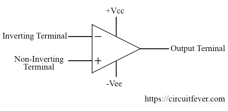
An op-amp has five terminals inverting terminal, a non-inverting terminal, an output terminal and two of them are for the supply voltage (+Vcc and -Vee).
The inverting op-amp
An op-amp can be operated as an inverting amplifier by applying input voltage at the inverting terminal of the op-amp through an input resistance Ri. Additionally, the non-inverting terminal is grounded as shown in below figure.
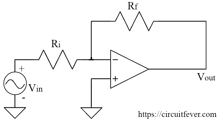
The output is feedback to the inverting terminal through a feedback resistor Rf.
In this configuration, the output will be inverted i.e 180 degrees out of phase as compared to the input signal or it is of opposite polarity.
Output voltage
$$V_o=AV_{in}$$
Where A is the closed-loop gain if op-amp and Vin is the applied input voltage.
$$A=-{R_f \over R_i}$$
So,
$$V_o=-V_{in}{R_f \over R_i}$$
Hence the output voltage of inverting op-amp is equal to the ratio of the feedback resistor and the input resistor multiplied by the applied input voltage. The negative sign indicates that output voltage is inverted or the reverse polarity as compared to the input voltage.
Some points to be noted about inverting amplifier
- The closed-loop gain of the inverting amplifier is the ratio of the feedback resistor and the input resistor
- If Rf=Ri, then the circuit provides a unity voltage gain with 180 degrees phase shift or reverse polarity.
The non-inverting op-amp
An op-amp can be operated as a non-inverting amplifier by applying input voltage at the non-inverting terminal of the op-amp. Additionally, the input resistor Ri which is connected to the inverting terminal is grounded as shown in below figure.
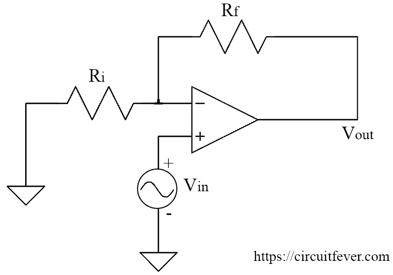
The output is feedback to the inverting terminal through a feedback resistor Rf.
In this configuration, the output will be in the same phase or it is of the same polarity as compared to the input signal.
Output voltage
$$V_o=AV_{in}$$
Where A is closed-loop gain if op-amp and Vin is the applied input voltage.
$$A=1+{R_f \over R_i}$$
So,
$$V_o=(1+{R_f \over R_i})V_{in}$$
Some points to be noted about non-inverting amplifier
- The voltage gain on the non-inverting amplifier can be made greater than 1.
- Voltage gain is positive.
- The voltage gain of the non-inverting amplifier will be greater than an equivalent inverting amplifier.