What is Pull-up and Pull-Down Resistor?
Pull-up and pull-down resistor are two different circuits used to set up external signal for hardware interrupt or preset signal.
It may have happened to you that, you interface a button or set an external hardware interrupt. You did very well but the behaviour of the system is undesirable. If this happened with you, you may definitely forget about these two circuits.
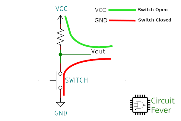
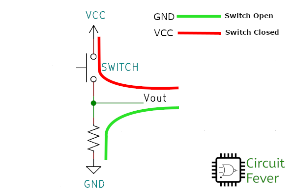
Let us try to understand these two circuits. Both the circuit has three points VCC, GND and Vout. VCC is logic 1, GND is logic 0 and Vout is output logic. Output can be either logic 0 or logic 1. Let's find out how both circuits work and how to use it.
Pull-up resistor
The resistor is connected upward of the output terminal. Assume that we do nothing to the circuit and button is not pressed. In this condition, the Vout is in parallel with the VCC. That's why the output will be logic 1.
Now assume that press the button or interrupt the circuit. Vout connects directly to the GND. That's why output will be logic 0.
Now, analyze the circuit. We do nothing to the circuit, the output is logic 1 and when we interrupt the circuit, the output is logic 0. We can say that output triggers from logic 1 to logic 0. It is a falling edge trigger circuit.

This circuit is used where we want to set logic 1 or where we want to set falling edge trigger interrupt.
Pull-down resistor
This circuit is just opposite to the pull-up resistor. The resistor is connected down to the output terminal. It makes output to logic 0 when there is no interrupt or button is not pressed.
When we press the button or interrupt the circuit, the output terminal connects to the VCC and it makes output to logic 1. The output triggers from logic 0 to logic 1. It is a rising edge trigger circuit.

This circuit is used where we want to set logic 0 or where we want to set rising edge-triggered interrupt.
Here is a tip:
If you want to set up an external hardware interrupt, it is recommended to use pull-up or pull-down resistor. Some microcontroller comes with an internal pull-up resistor that has to be configured using the program. But if you not sure about the internal circuit, use an external one.
If you want to interface button with the microcontroller, don't forget to use one of these two circuits.
