
Ripple Carry Adder
Ripple carry adder is a combinational circuit that can perform addition operation of two n-bit binary numbers. It accepts two n-bit binary numbers as an inputs, performs addition of both the binary numbers and generated it's addiiton as an output. You'll find easy to understand this topic if you know full adder how the full adder circuit works. If you do not know how full adder works, let us understand full Adder illustrating it as a black box
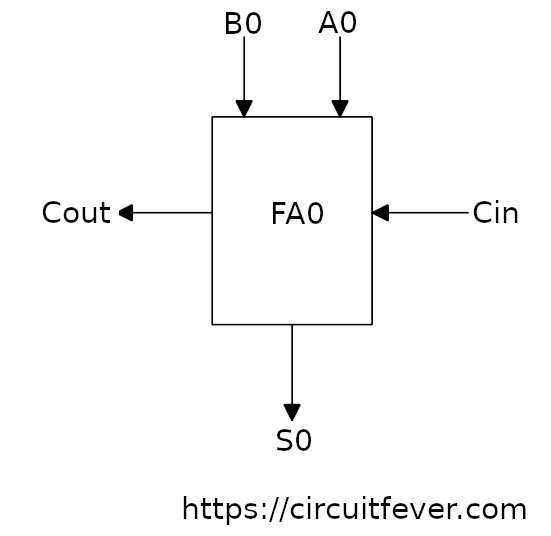
Full-Adder as a black box
Full-adder is a combinational circuit which has three inputs and two outputs. It basically performs the addition of 3-bits. When we add three binary bits, Sum and Carry is generated based on the binary inputs. The truth table of Full adder is given below
Truth table of full-adder circuit
| Input A0 | Input B0 | Input Cin | Output S0 | Output Cout |
| 0 | 0 | 0 | 0 | 0 |
| 0 | 0 | 1 | 1 | 0 |
| 0 | 1 | 0 | 1 | 0 |
| 0 | 1 | 1 | 0 | 1 |
| 1 | 0 | 0 | 1 | 0 |
| 1 | 0 | 1 | 0 | 1 |
| 1 | 1 | 0 | 0 | 1 |
| 1 | 1 | 1 | 1 | 1 |
n-bit Ripple carry adder
Ripple carry adder is designed by connecting full-adder circuits in a cascade fasion in such a way that, two n-bit binary inputs are applied parallelly to the circuit and the output carry of previous full adder is applied to the input carry of the next full adder. For two n-bit binary addition, n number of full adder circuit is required. generated
This circuit generates output of n-bit sum with output carry of cumulative sum. Let's try to understand how the citcuit is working. For simplicity, 4-bit ripple carry adder is designed. In this circuit, there are two four bit numbers [A3, A2, A1, A0] and [B3, B2, B1, B0] and we want to perform addtion of these two binary numbers.
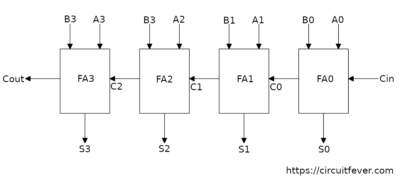
These two 4-bit binary numbers are applied to the circuit such that first biary position (LSB) is the input of Full-Adder (FA0), second binary position to the second Full-Adder (FA1) circuit and so on.
FA0 performs the addition operation for first binary position [A0 and B0]. Depending on the inputs, sum S0 and carry C0 is generated. Here we get first bit of the sum which is S0.
FA1 performs the addtion operation for second binary position [A1 and B1] and carry [C0] comming from the FA0 and generted sum S1 and carry C1. Here we get second bit of the sum S1, and so on.
For the last full adder, final bit of the sum [S3] and carry out [Cout] is generated. Finally we get sum [S3, S2, S1, S0] and carry [Cout].
So, this is the simple circuit for performing two n-bit addition operation. All we need is n number of full adder circuit.
Some problems
The inputs are applied parrally to the circuit in the same time but, we'll not get the output in the same time. Why?
Even though inputs are available to the all full adder circuit, Sum of any position is depending on carry comming from the previous full adder.For the final addition operation, the propagation delay is four full-adder circuit (for 4-bit ripple carry adder). If the number of inputs are more bits (say 8-bits), there will be more propagation delay So, this circuit is not suitable for adding large input bits.