Ripple Carry Adder Verilog Code
Ripple carry adder is a combinational circuit which computer n-bit addition of two binary number.
Ripple Carry Adder Verilog Code
First create a module for full adder and describe full adder in it. The boolean expression for full adder is $$sum = a \oplus b \oplus cin$$ and $$carry = a.b + b.cin + cin.a$$
Below is the Verilog code for full adder described using data flow modeling.
module full_adder(
    input a,b,cin,
    output sum,carry);

assign sum = a ^ b ^ cin;
assign carry = (a & b)|(b & cin)|(cin & a);

endmodule
Now create another module for ripple carry adder in which we instantiate the above full adder code and describe a 4-bit ripple carry adder.
Create a module name rca and declare input output ports. Here inputs a and b are 4-bits thats why we are using vector declaration of input a and b. [3:0]a means we have 4 inpts of a which is a[0],a[1],a[2],a[3]. Similar is for input b and output sum. cin and c4 are 1-bit input that's why we have declare it seperaelly.
module rca(
    input [3:0]a,b,
    input cin,
    output [3:0]sum,
    output c4);

endmodule
Now instantiate four full adder with unique instance name. I am using fa0,fa1,fa2 and fa3 as four instance of full adder (or four copy of full adder)
module rca(
    input [3:0]a,b,
    input cin,
    output [3:0]sum,
    output c4);

full_adder fa0();
full_adder fa1();
full_adder fa2();
full_adder fa3();

endmodule
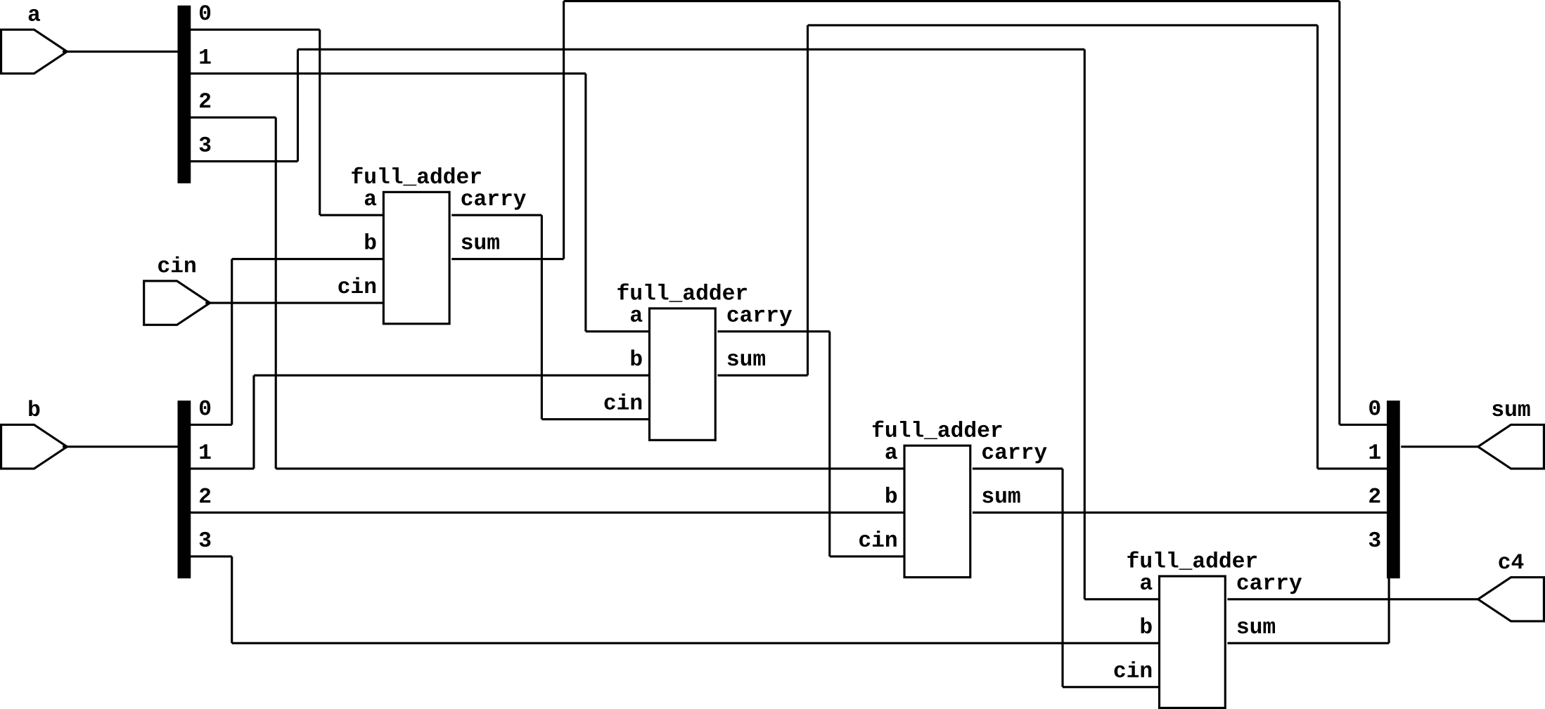
Other that full adder, we have three internal connection for carry out form previous full adder. Let's declare them as three wire c1,c2 and c3. Make all the connections with module and full adder. Carry in of full adder is the carry out of previous full adder.
Here is the complete Verilog code of 4-bit ripple carry adder
module rca(
    input [3:0]a,b,
    input cin,
    output [3:0]sum,
    output c4);

wire c1,c2,c3;      //Carry out of each full adder

full_adder fa0(a[0],b[0],cin,sum[0],c1);
full_adder fa1(a[1],b[1],c1,sum[1],c2);
full_adder fa2(a[2],b[2],c2,sum[2],c3);
full_adder fa3(a[3],b[3],c3,sum[3],c4);

endmodule
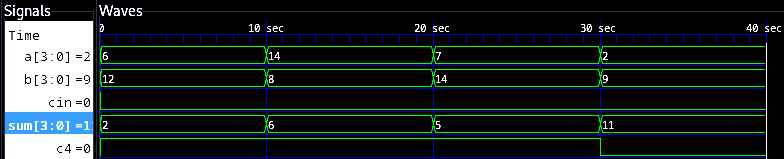
Ripple Carry Adder Testbench
The testbench for testing 4-bit ripple carry adder is given below. We have taken four random inputs but you can take as many input you want.
module rca_tb;
reg [3:0]a,b;
reg cin;
wire [3:0]sum;
wire c4;

rca uut(a,b,cin,sum,c4);

initial begin
cin = 0;
a = 4'b0110;
b = 4'b1100;
#10
a = 4'b1110;
b = 4'b1000;
#10
a = 4'b0111;
b = 4'b1110;
#10
a = 4'b0010;
b = 4'b1001;
#10
$finish();
end

endmodule