
Structural Modeling In Verilog
After switch level modeling, Structural modeling is the lowest level of abstraction in verilog. It is also called gate level modeling because we only describe a hardware in logic gates and their inteconnections.
Keywords Required
- and()
- or()
- not()
- nand()
- nor()
- xor()
- xnor()
- wire
In above keywords of logic gates, inside the parentheses we are required to list input and output connections. In all of the above logic gate keywords, first list will be output and rest will be inputs. For example and(y,a,b); instantiate a AND gate with output y and inputs a,b.
Using wire keyword, you can make internal connections between the logic gates. To make internal connections, we are required to declare the internal wire name. For exmaple wire x; will declare a wire which has name x.
Describe a hardware using these keyowrds
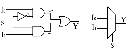
Let us describe a 2X1 MUX using structural modeling. Write the boolean expression and make a logic circuit diagram.
Boolean Expression
$$Y = \bar S I_0 + S I_1$$
Circuit Diagram
Let's describe 2X1 MUX in Verilog
First, create a module and define input output ports. Make logic gates by instantiating respective logic gate keyword. There is two AND gate, one OR gate and one NOT gate.
/*
  Module     : mux2x1_struct.v
  Created By : circuitfever.com
  Create on  : 22-01-2023
*/
module mux2x1(
    input I0,I1,S,
    output Y
    );

not();
and();
and();
or();
endmodule
Declare internal connection using wire keyword.
/*
  Module     : mux2x1_struct.v
  Created By : circuitfever.com
  Create on  : 22-01-2023
*/
module mux2x1(
    input I0,I1,S,
    output Y
    );
wire w1,w2,w3;
not();
and();
and();
or();
endmodule
Now make connection between logic gates and input output ports.
/*
  Module     : mux2x1_struct.v
  Created By : circuitfever.com
  Create on  : 22-01-2023
*/
module mux2x1(
    input I0,I1,S,
    output Y
    );
wire w1,w2,w3;
not(w1,S);
and(w2,I0,w1);
and(w3,I1,S);
or(Y,w2,w3);
endmodule
After making connections, synthesize the design and you'll see the output diagram of your described hardware.