
How to Simulate Verilog HDL on Vivado 2022
For this tutorial we are using Xilinx Vivado 2022for simulating Verilog HDL. But you can also simulate this is older or newer version of the AMD Vivado.
Create New Vivado Project
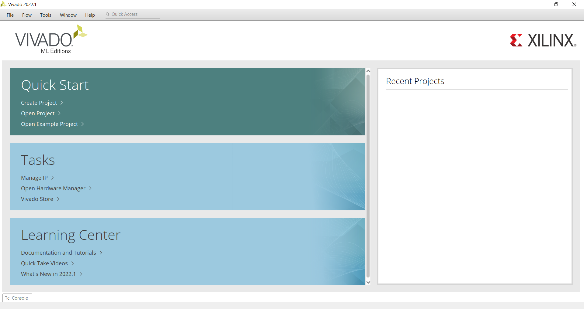
In this part we'll create a Vivado Project. Open Vivado 2022, The window of Vivado 2022 looks like as shown below. If you are using previous verison of Vivado it may look different.
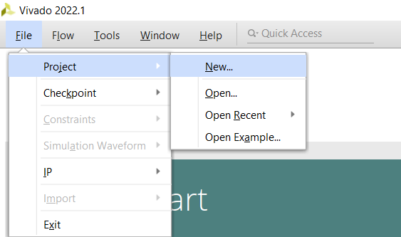
Click on File → Project → New
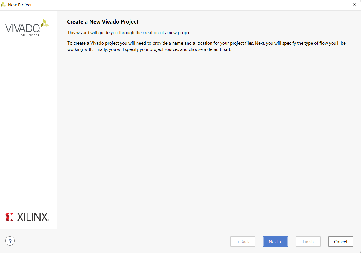
New Project Window will apprer. Click on Next
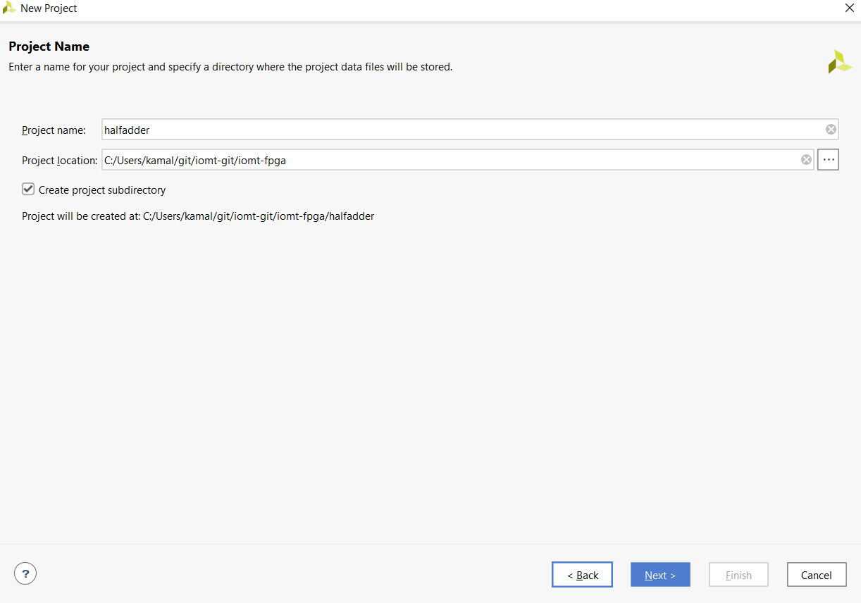
In project Name, write a unique project name and Click Next. Do not forget to check Create project subdirectory
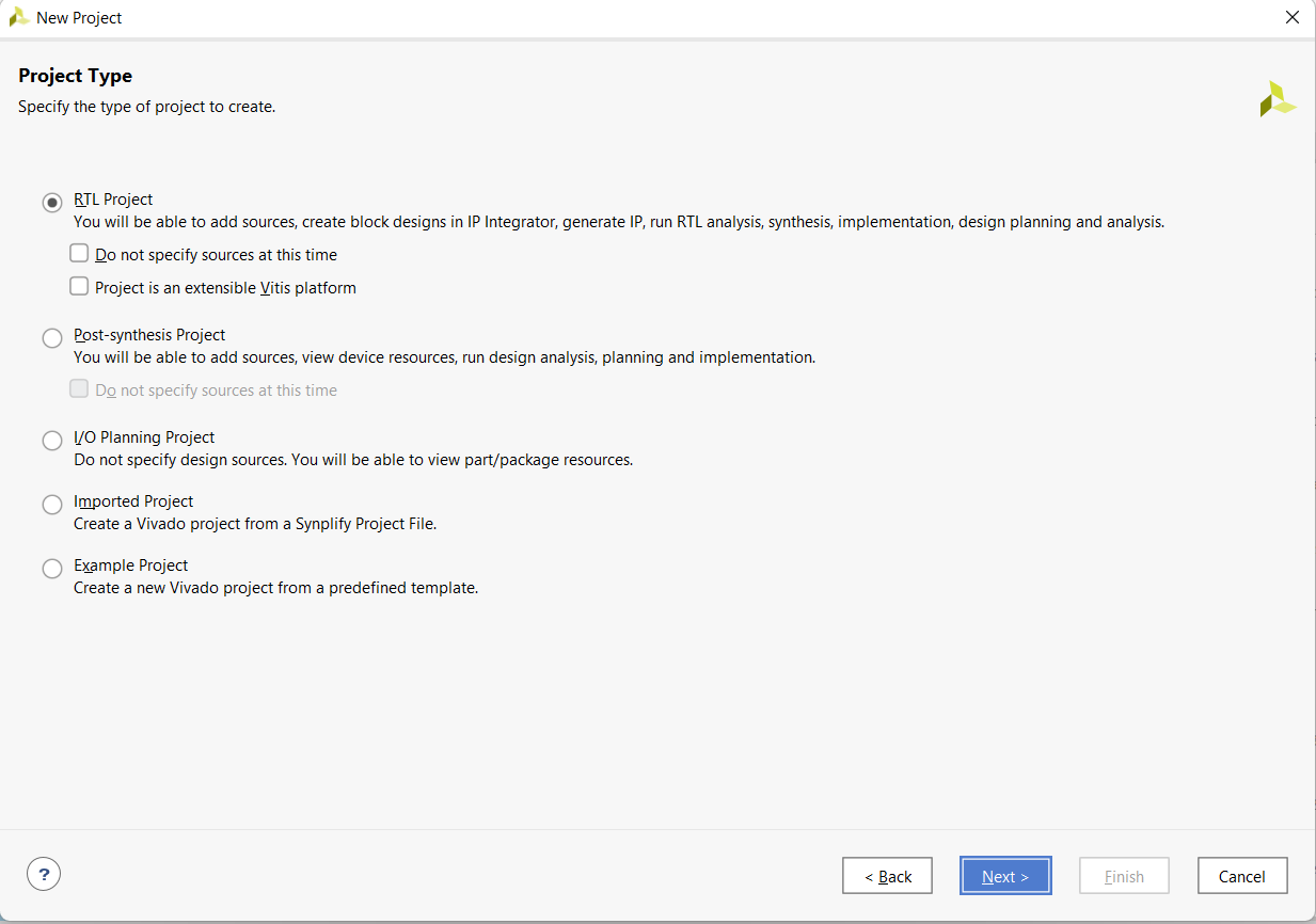
Choose RTL Project
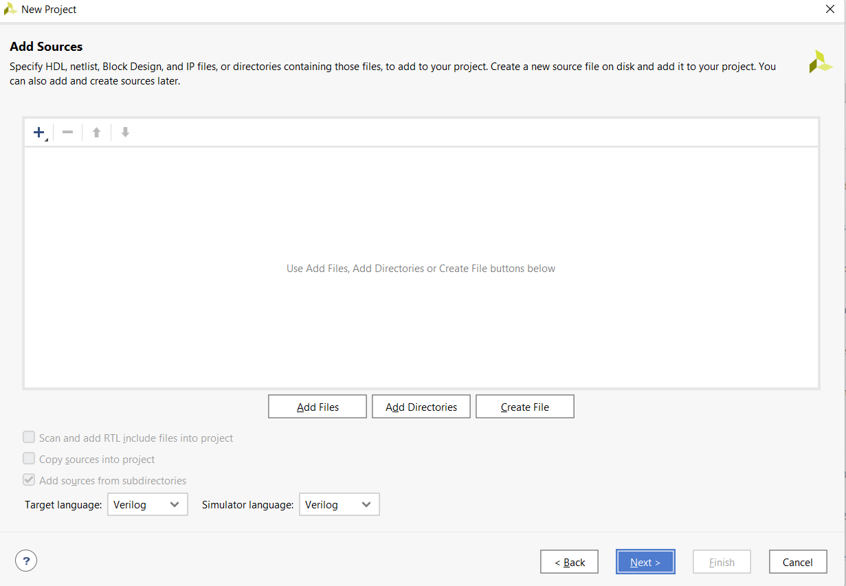
You can add Source file from here. For this tutorial skip this part (Click Next). We'll Create source file later
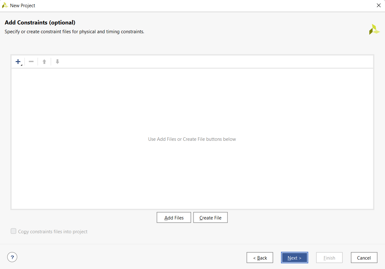
We do not require any Constraints File so, skip this part by cliking on Next
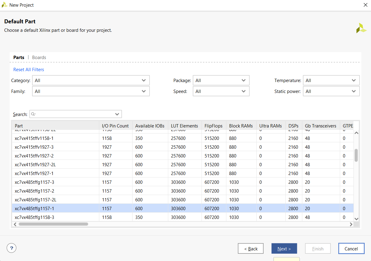
Do not choose any part number since we are just simulating the Verilog HDL so leave it as default part. Click Next
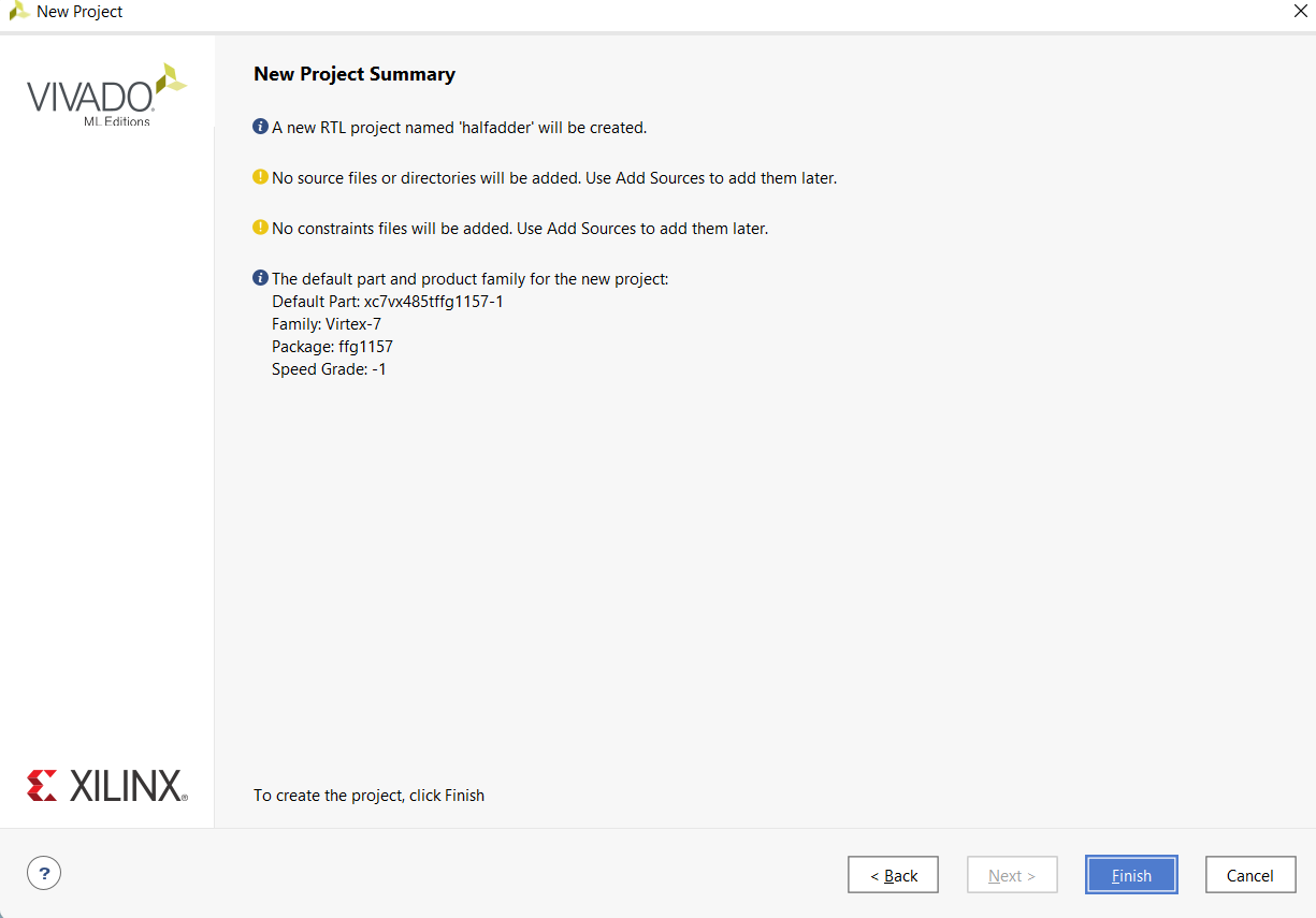
In this window, project summary will show. Click on Finish
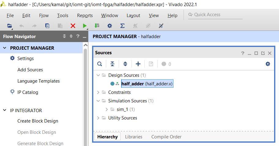
After creating the project, the will look like as shown below.
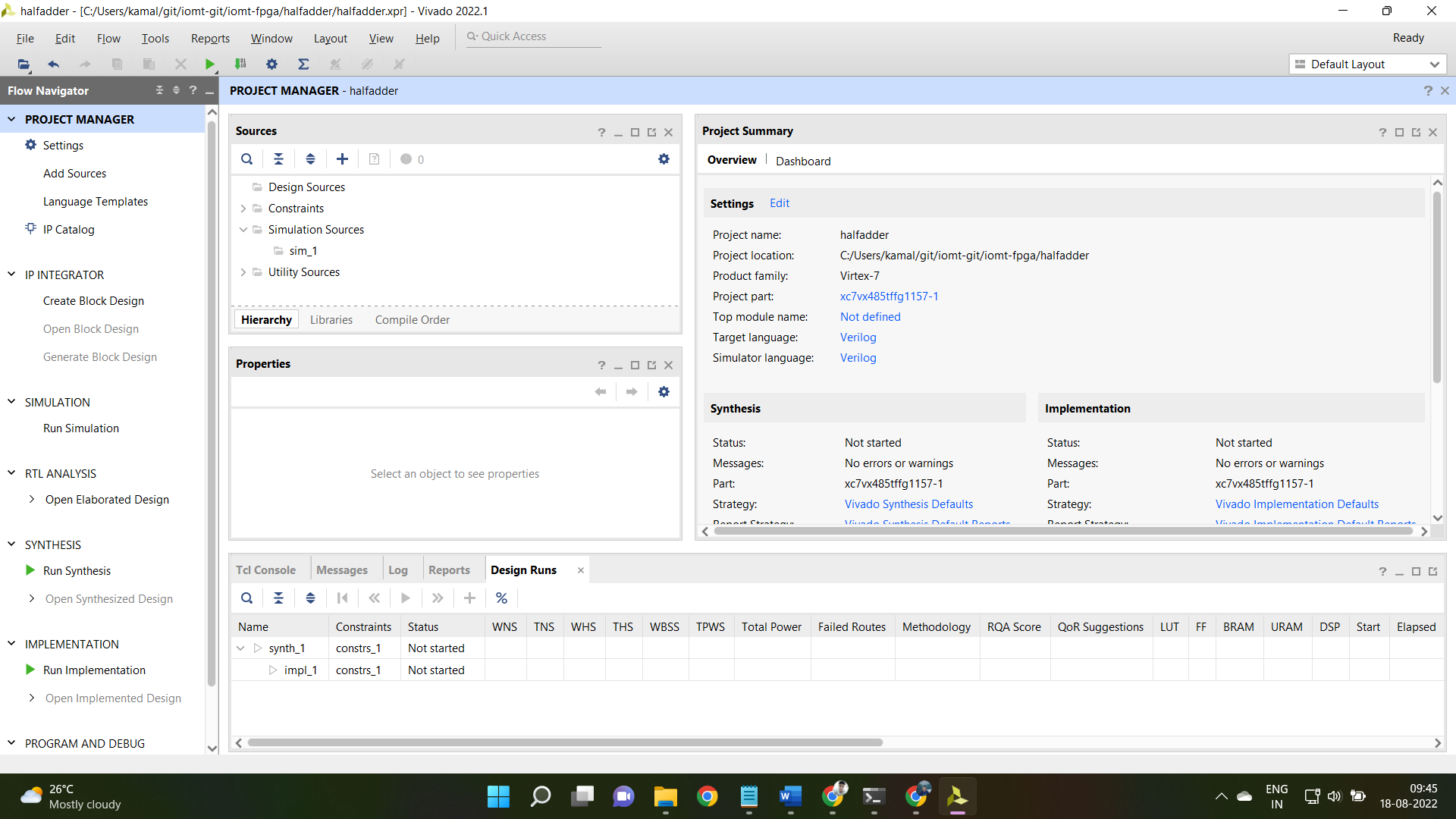
Till now, we've created the Vivado Project required for this tutorial.
Create Design Source
Now, we'll create source file for writing Verilog HDL.
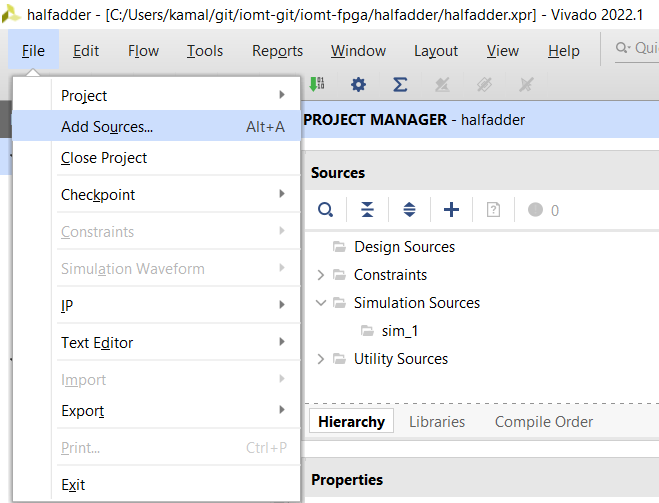
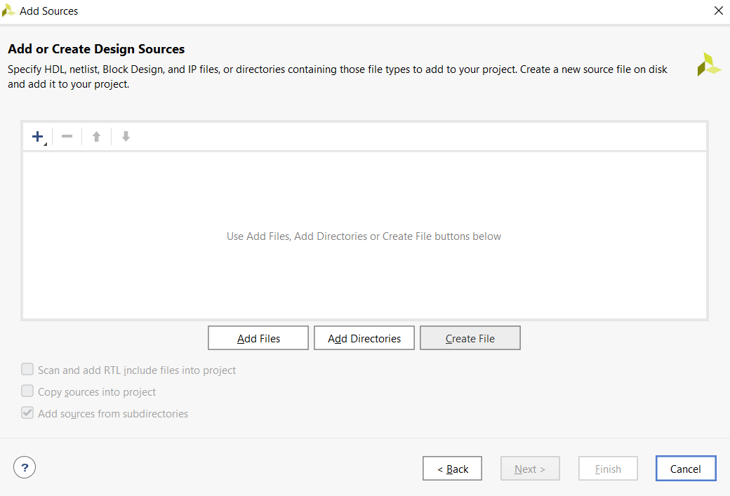
Click on File → Add Sources
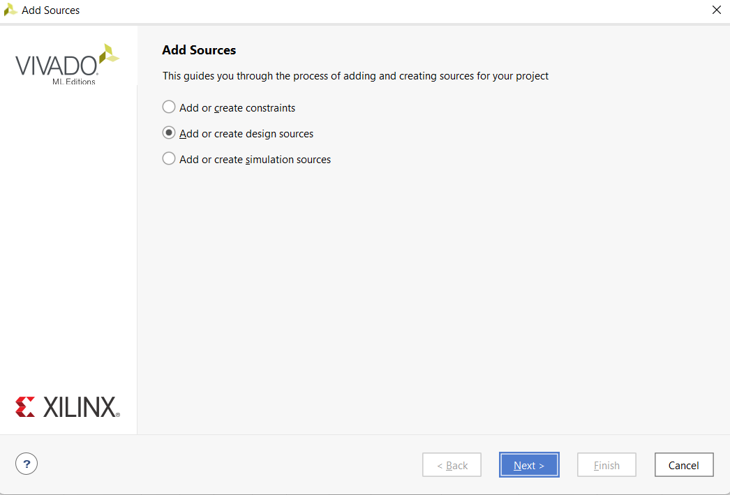
Click on Create Design Source and click on Next
Click on Create File
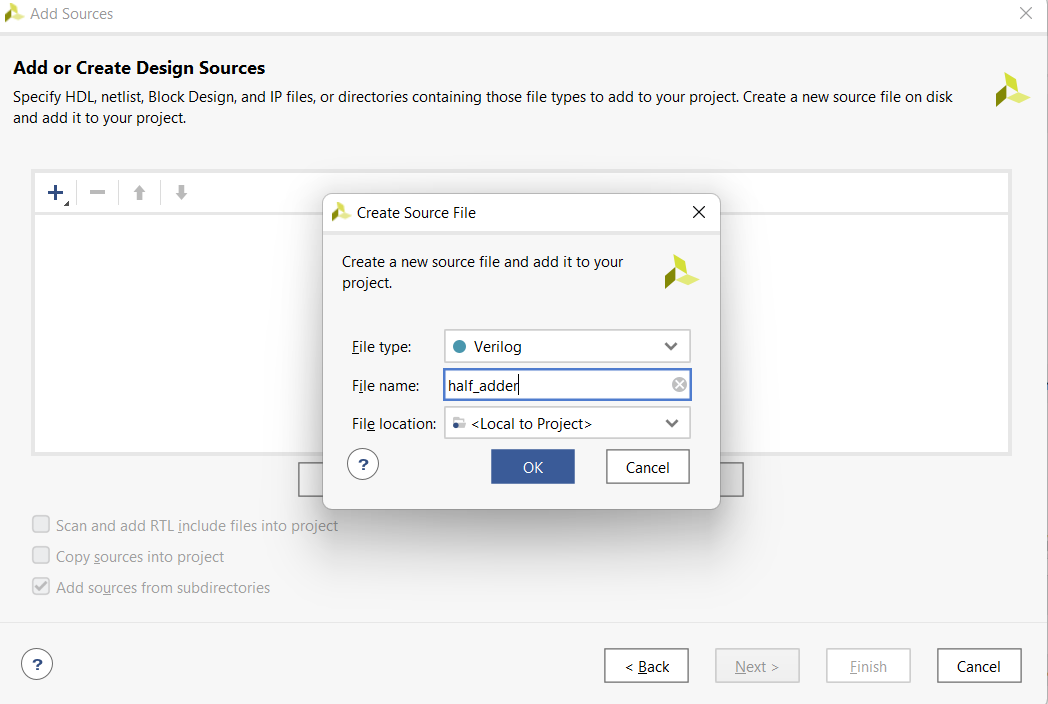
Write a unique file name and click OK
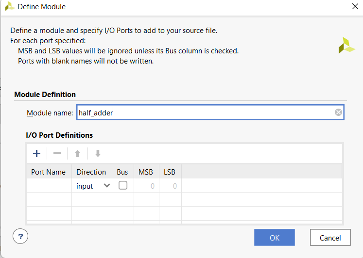
In this window you can define your module name and input output ports. Do not change the module name and click OK
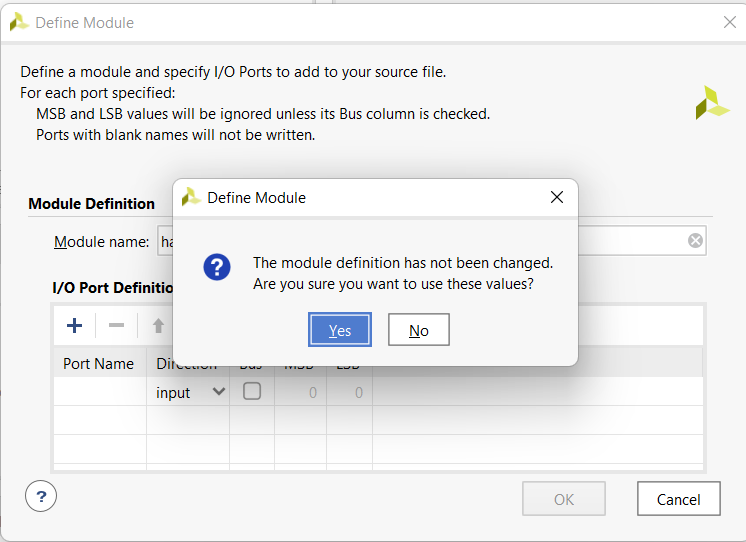
Click Yes
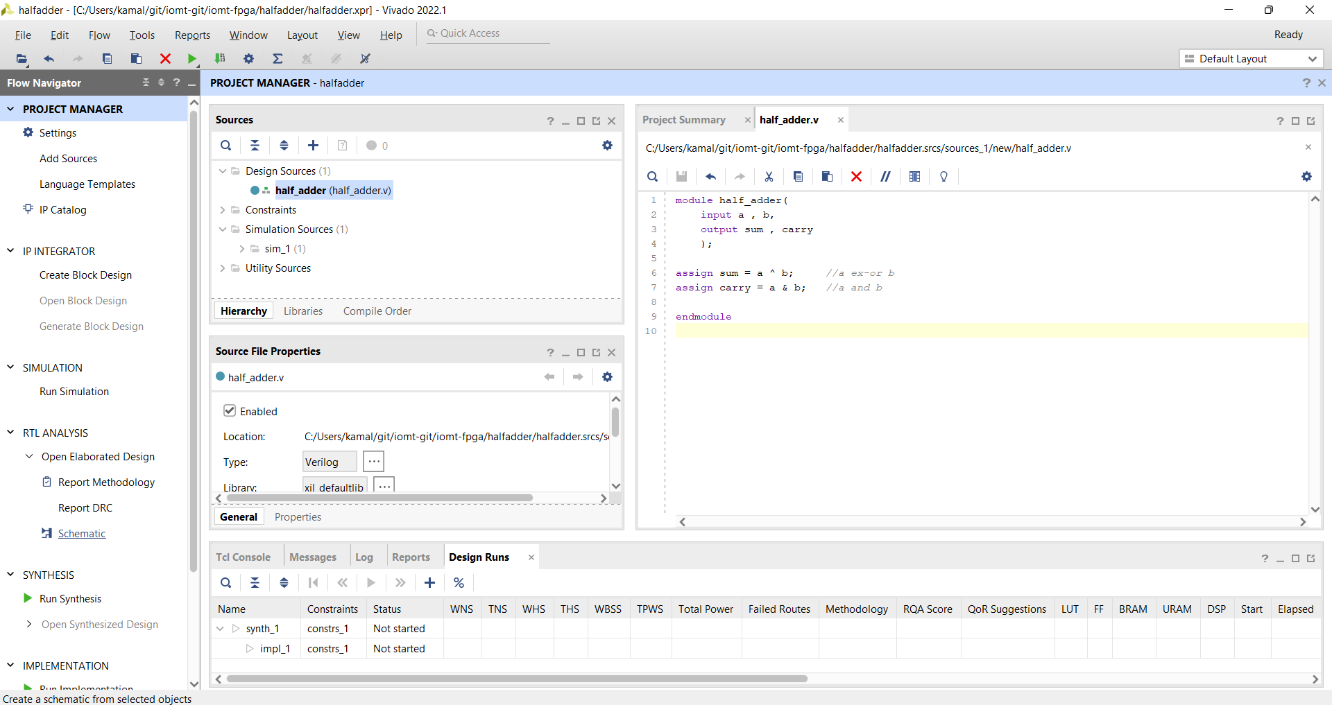
In Project Manager, Under the Design Sources you can find your all design files. Double clik on this to write Verilog codes.
Write the Verilog Code. The code for half adder is given below. This module has two inputs and two outputs
module half_adder(
    input a , b,
    output sum , carry
    );

assign sum = a ^ b;     //a ex-or b
assign carry = a & b;   //a and b

endmodule
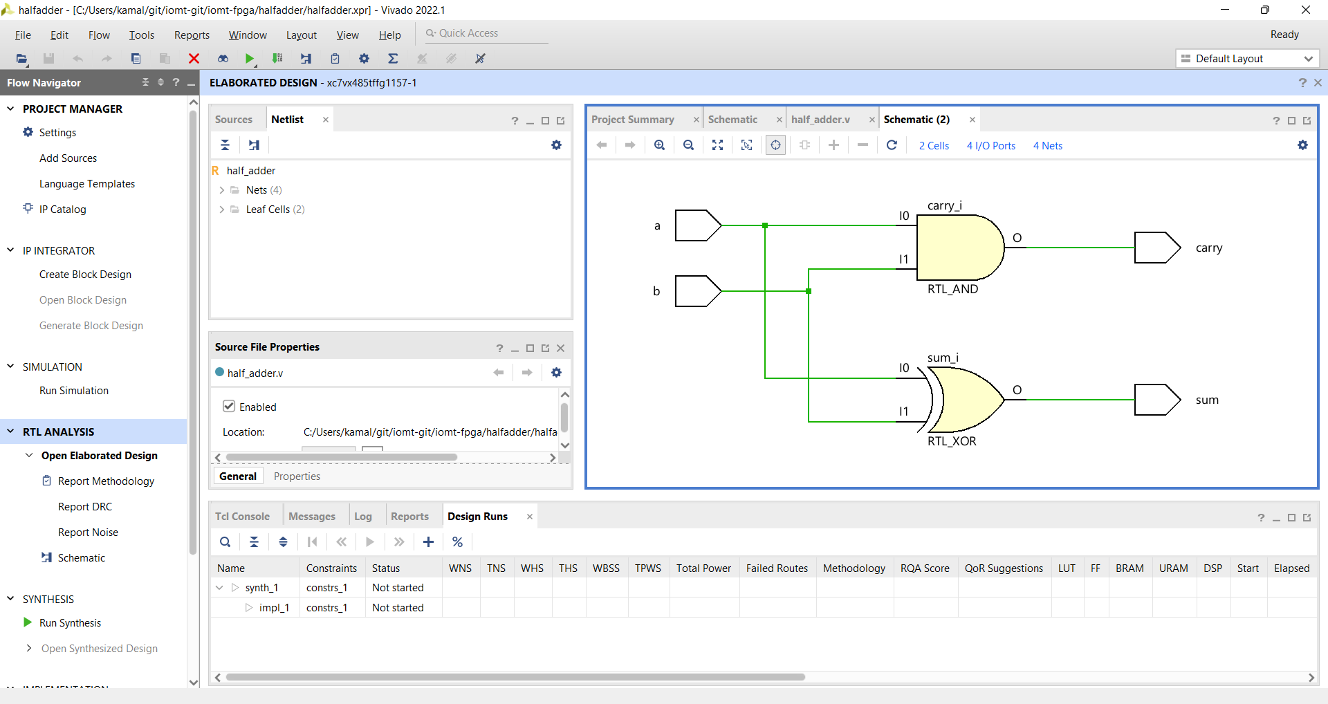
You can check the RTL Schematic. To do this, In Project manager (Left side of the window), Click on RTL Analysis →Schematic
Create Simulation Source
Now our module is ready. We'll now create Test Bench for testing this module.
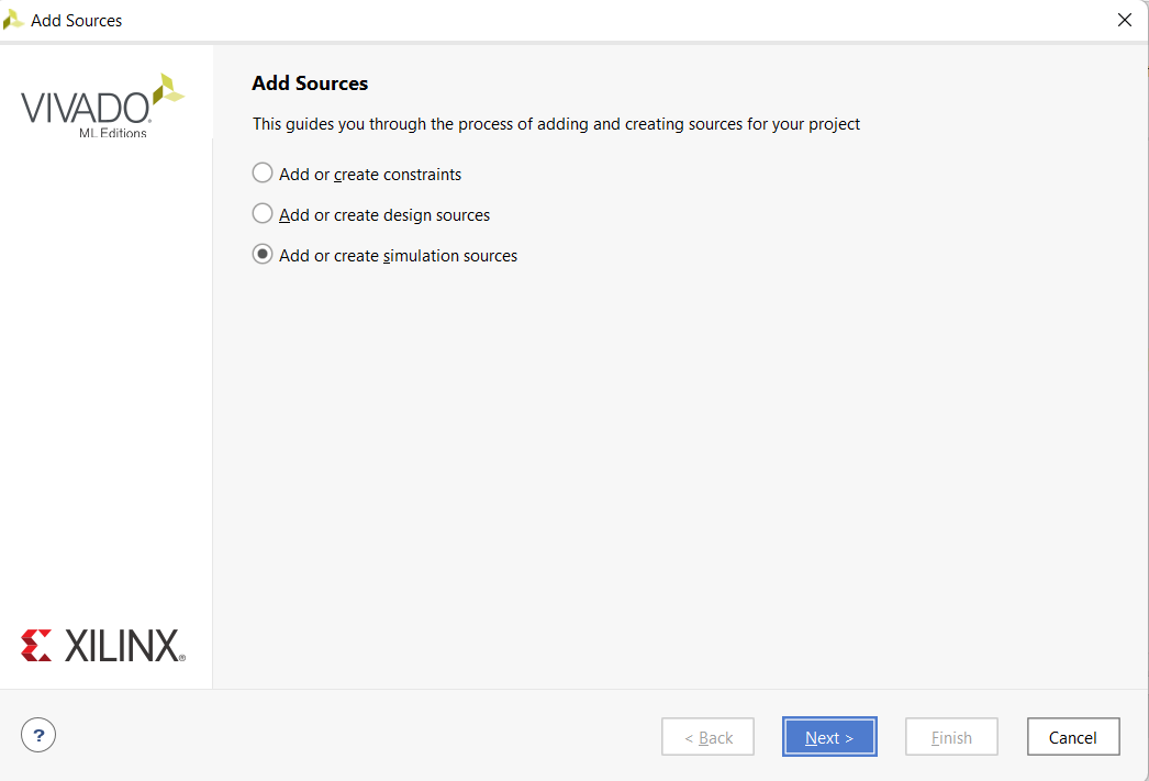
Click on File → Add Sources and do no forget to click on Add or Create Simulation Sources
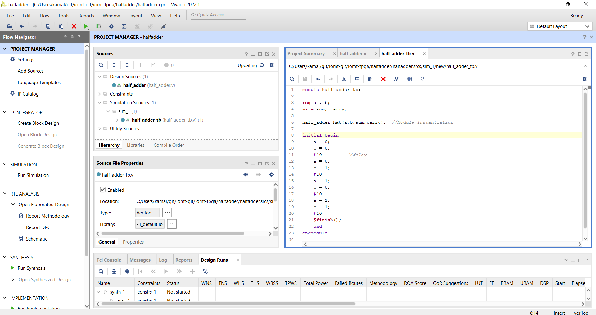
Write the verilog code for test bench
module half_adder_tb;

reg a , b;
wire sum, carry;

half_adder ha0(a,b,sum,carry);  //Module Instantiation

initial begin
    a = 0;
    b = 0;
    #10         //delay
    a = 0;
    b = 1;
    #10
    a = 1;
    b = 0;
    #10
    a = 1;
    b = 1;
    #10
    $finish();
    end
endmodule
Click on Simulations → Run Simulation. Now you can see the waveform
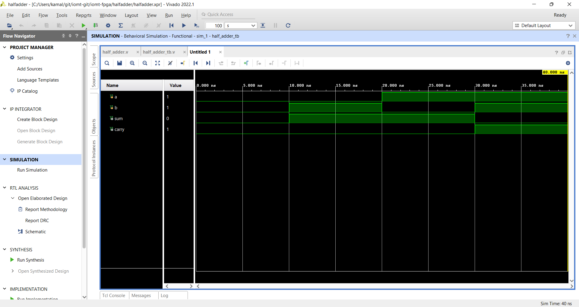
That's all.