Adder-Subtractor Verilog Code
Adder Subtractor circuit is the arithmetic digital circuit which can perform both addition and subtraction using only one n-bit adder, no seperate circuit for addition or subtraciton is required.
Adder-Subtractor Verilog Code
The logic of the circuit is that, we can represent a negative number in 2's complement number system by taking it's complement and then adding 1 into it. So, if we want wo perform operation y = A - B, we can perform y = A + (-B) and the result is same y = A - B. So, we require only adder to perform subtraction operation if we can convert positive input to the negative input. $$ y = A + (\overline B + 1)$$ $$y = A + (-B)$$ $$y = A - B$$
We need to implement an adder. Let's use n-bit Ripple Carry Adder for this. Now, only we need to write code to implement the n-bit inverter to make one input negetive number. If carry in (Cin) is logic 1 and one number is negetive, the adder will compute y = A-B. If carry in is logic zero and both the number is same as the input, then it computer y = A + B.
//4-bit adder subtractor
module add_sub(
    input a_s,
    input [3:0]A,B,
    output [3:0]sum_diff,
    output carry_brrow
);

wire [3:0]Bmod;

assign Bmod = {4{a_s}} ^ B;

rca rca0(A,Bmod,a_s,sum_diff,carry_brrow);

endmodule
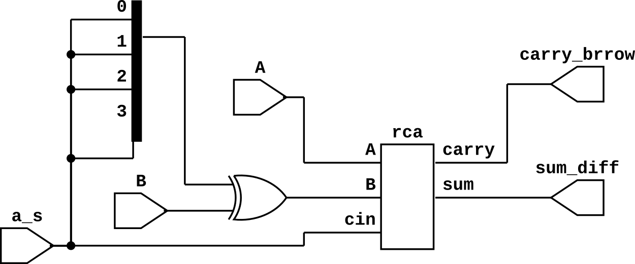
The complete Verilog code for n-bit adder-subtractor circuit is given above. There are two inputs numbers A,B and one input (a_s) for performing adder/subtraction. The input a_s is connected to the cin of the ripple carry adder. A is directly connected to the input A of ripple carry adder and B is connected to the one input of n-bit ex-or gates. So wire Bmod is B when input a_s is 0. Wire Bmod is complement of B if a_s is 1.
The circuit diagram of the above code is shown below. As we can see in the circuit diagram, input B of the ripple carry is the output of the ex-or gate. It is equal to B if a_s is logic 0, hence the output of the adder is A + B and it is complement of B if a_s is 1, a_s is also connected to the cin of the adder so, the output of the adder is A - B.
Adder subtractor Testbench
module add_sub_tb;

reg a_s;
reg [3:0]A,B;
wire [3:0]sum_diff;
wire carry_borrow;

add_sub uut(a_s,A,B,sum_diff,carry_brrow);

initial begin
A = 5; B = 3;
a_s = 0; //Additin
#20
a_s = 1; //Subtraction
#20
$finish();
end

endmodule
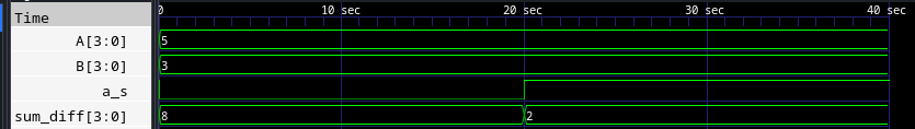
Output Waveform