Seven Segment Display Driver On FPGA using Verilog
Seven segment display is a basic display used to show numbers, and it is widely used in many electronics devices. One digit seven segment has eight pins however, the microcontroller or the processor has limited input/output pins. If we want to use more than one seven segment digit, we require lots of input/output pins.
To reduce the pin count, all multi-digi seven segment display has common data pins, and seperate enable pin. For displaying digit to a perticular digit, the respective enable pin should be set and the data digit should be the number we want to display in that digit.
This can be done by changing enable pin and data pins sequentially so that if digit 0 is enabled, the data pins should have the number we want to display at digit 0 and so on. In this tutorial, we'll implement 4-digit display driver.
7-Segment Display Decoder
First hardware requirement to implement our driver is seven segment decoder. If you do not know how to implement this read this post on How to implement 7 segment display decoder using Verilog. We'll be using the same decoder for our driver Verilog code.
Verilog Code
Let's start with the outputs of the 7-segment decoders. There are 4-digit so four 8-bit input are taken. This inputs will be connected to the four decoders. Teh below code has the simple FSM(Finite State Machine) which has two states, first it loads the decoder outputs to the 32 bit register, then it enables the digit 0 in second state.
In second state, it shift the enable by 1 bit and shift loaded decoder data by 8 bit. Which shift the enable to the next digit with the respective digit data. When all digits are displayed, it again load the data. If there is any change in the display digit number, it will be reflected once all the previous data is displayed.
module seg7driver(
    input clk,
    input [7:0]dataseg3,dataseg2,dataseg1,dataseg0,
    output reg [3:0]AN,
    output [7:0]segment
    );

assign segment = data_to_display[7:0];

reg state;
reg [1:0]count;
reg [31:0] data_to_display;

always @(posedge clk) begin
case (state)
    0: begin
        AN <= 4'h8;
        data_to_display <= {dataseg3,dataseg2,dataseg1,dataseg0};
        state <= 1;
        count <= 0;
    end
    1: begin
        count <= count + 1;
        data_to_display <= data_to_display >> 8;
        AN <= AN >> 1;
        if(count == 3)
            state <= 0;
    end

    default : state <= 0;
endcase
end

endmodule
Top Module
The above code can display the something to the display but we need a decoder for showing digits properlly. The below top module connects the decoder and driver so that the driver can display numbers. Most of the FPGA has high frequency clock and we do not require high frequency clock.
For slowing down the clock, the clock divider circuit is implemented. The sytem clock can be connected to this clock divider, which basically slows down the clock. The clock can be connected to the driver.
module top(
    input clk,
    output [3:0]digit,
    output [7:0]segment
    );

wire [3:0]d0=1,d1=2,d2=3,d3=4;
wire [7:0]seg0,seg1,seg2,seg3;


seg7decoder dgit0(d0,seg0);
seg7decoder dgit1(d1,seg1);
seg7decoder dgit2(d2,seg2);
seg7decoder dgit3(d3,seg3);

//-------------------- Slow down the clock --------
reg clk_out;
reg [15:0] count;

always @(posedge clk) begin
    count <= count + 1;
    if(count < 32768)
        clk_out <= 0;
    else
        clk_out <= 1;
end

//------------- 4 digit seven segment driver -------
seg7driver driver(clk_out,seg3,seg2,seg1,seg0,digit,segment);

endmodule
FPGA Implementation
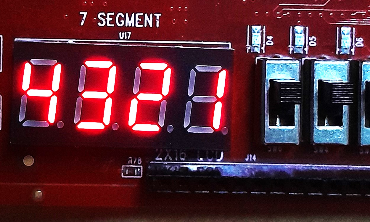
Connect the segment port to the common data bus of the display and connect digit to the enable pin of the display. The system clock can be directly connected to the clk pin of the top module. To find out which one is digit 0 or digit 3, check the datasheet of the respective seven segment display. The output of the above Verilog code is shown below.